0 mounting on the roof curb with the maps, Unit – Reznor MAPS IV Option - Installation - Energy Recovery Module Installation User Manual
Page 3
I-MAPSIII&IV-ER, PN262634R3, page 3
The module is shipped separately and must be lifted to the roof curb AFTER the MAPS
®
unit is in place. Some preparation is required before the module can be mated to the
MAPS
®
unit. Refer to the illustration and follow the instructions below.
Lifting and Mating
the Energy Recovery
Module and MAPS
®
Unit
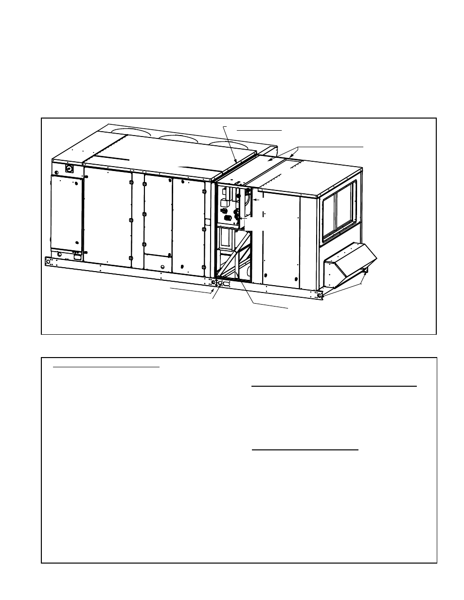
3b&c) All Sizes - After
lifting, before mating
to the MAPS® unit,
remove both the
module top panel and
non-control side panel
closest to MAPS® unit.
3a) All Sizes - After lifting, before
mating to the MAPS® unit, remove
control access panel door.
1) Cabinet C only - Prepare MAPS® unit by removing
screws from edge of MAPS® unit top.
Option ER1C - Energy
Recovery
Module
4) All Sizes - Lower the module on to
the roof curb, mating the curb caps.
Install splice plate (not shown) here
on both sides to join curb caps.
MAPS® Unit
(Cabinet C illustrated)
Electrical
Compartment
2) Lifting Points - (4)
one at each corner of
the module curb cap
2) Lifting Point
(NOTE: Use both holes
to attach rigging; do not
attach around end of curb.)
MAPS®
Unit
Coil
Access
Door
MAPS® Unit
Blower and
Motor Access
MAPS®
Control
Panel
Filter Access
and
Reheat Compressor on RDB,
RDDB, REDB, RDC,
RDDC, & REDC
Supply Fan
Access
1. Cabinet Size C (Option ER1C) - Prepare the MAPS
®
Cabinet C unit by removing the screws from the edge
of the top.
2. Rig the module using all four lifting points and
spreader bars. When attaching rigging, attach from
the sides being sure that there will be no interference
with mating to the MAPS
®
unit.
Carefully, lift and position the module but DO NOT set
it on the roof curb.
3. Prepare the Module (BEFORE setting it on the curb)
a) On the control side of the module, remove the access
panel.
b) On the top of the module, remove the section that
is closest to the MAPS
®
unit.
c) On the non-control side, remove the panel that is
closest to the MAPS
®
unit.
d) Remove the parts package shipped inside the
cabinet and locate the splice plates and the 3/4”
screws.
4. Lower the module onto the roof curb, mating the
curb cap of the module to the curb cap of the unit. Use
the 3/4” screws to attach a splice plate to each side
connecting the curb caps.
5. Cabinet Sizes A and B (Option ER1A or ER1B) -
With the curb caps joined, reposition the non-control
side panel and the top panel section removed in Steps
3b) and 3c). The top of the module will extend over
the MAPS
®
unit. Re-attach both panels to the module.
Use sheetmetal screws to attach the module top to
the unit top.
Cabinet Size C (Option ER1C) - With the curb caps
joined, replace the non-control side panel removed in
Step 3c). Slide the lip of the module top section under
the edge of the MAPS
®
cabinet top panel and replace
the screws removed in Step 1.
Re-attach the top section of the module.
6. Before replacing the control access panel, match
the connector colors and join the energy recovery
wires to the wires from the MAPS
®
unit. (See
illustration on page 4.)
Refer to the unit wiring diagram and connect the
power supply wires to the distribution blocks.
Replace the control access panel.
A MAPS
®
unit that includes an Optional ER1 energy recovery module requires an
optional roof curb designed to include the field-attached energy recovery module. Roof
curb Option CJ34, CJ53, or CJ54 must be installed and the MAPS
®
unit in place before
the energy recovery module is lifted to the curb. Follow the instructions provided with
the curb and the MAPS
®
unit.
4.0 Mounting
on the Roof
Curb with the
MAPS
®
Unit
INSTRUCTIONS
(Steps apply to all sizes except where noted.)