0 maintenance and service (cont’d), Energy recovery wheel (cont’d) – Reznor MAPS IV Option - Installation - Energy Recovery Module Installation User Manual
Page 10
I-MAPSIII&IV-ER, PN262634R3, page 10
Energy Recovery
Wheel (cont’d)
Checking
the Seals
Check Wheel Drive Components
Motor - The motor bearings are pre-lubricated and do not need additional lubrication. Clean any dirt from the air cooling
ports in the motor housing.
Pulley - The pulley is secured to the drive motor shaft by a set screw. The set screw is secured with removable Locktite
to prevent loosening. Confirm the set screw is secure.
Belt - The belt is of urethane stretch material and is designed to provide constant tension. There is no type of adjust-
ment. Inspect the belt for proper tracking and tension. If a belt needs replaced, it must be replaced with a factory-
authorized replacement (see P/N’s below). Follow the wheel manufacturer’s instructions.
NOTE: A properly tensioned belt will turn the wheel immediately after power is applied with no visible slippage during
startup. The belt should track approximately 1/4” from the outer edge of the rim.
If the belt or any other component needs replaced, use only factory-authorized replacement designed for the purpose.
Follow instructions provided by the wheel manufacturer.
Wheel Replacement Parts
*See cross-reference of
MAPS
®
Models by Cabinet
Size A, B, or C on page 11.
10.0 Maintenance
and Service
(cont’d)
d) Repeat the procedure on the other three seals.
2. When the unit is started, start and stop the wheel several times to verify seal
adjustment and to confirm that the belt is tracking properly on the wheel rim. The
belt should be approximately 1/4” from the outer edge of the rim.
Part
Cabinet A *
Cabinet B *
Cabinet C *
Belt
262488
262489
262490
Wheel
Motor
115V, 1050
rpm
- 262494
200-230/480/3, 800 rpm
- 262491 200-230/480/3, 1075 rpm - 262492
575V, 1075 rpm -
262493
575V, 1075 rpm -
262493
Wheel
Segment
(1)
262495
(1)
262497
(1)
262499
(4)
262496
(6)
262498
(6)
262500
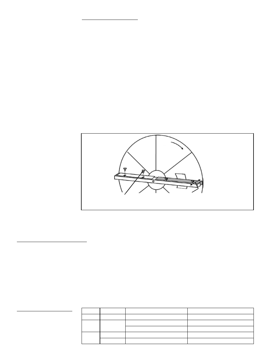
Checking the Wheel Seals - The seals are on the center support that goes across the
diameter of the wheel. There are two seals on each side of the wheel with one seal on
each side of the hub. Seals are metal strips with insulation on the surface closest to the
wheel. The purpose of the seals is to minimize the transfer of air between the counter
flowing airstreams.
After any wheel service and during maintenance, check the seal adjustment. Adjusting
the seals will require a screwdriver and a piece of paper.
1. If the wheel has not been removed from the cabinet, follow the steps in the
illustration on page 7 to remove the cassette.
Each seal strip has adjustable retaining screws that allow the insulation to move
toward or away from the wheel. Refer to the illustration below, and follow the
instructions below to adjust the seals.
a) On one seal, loosen the seal retaining screws just enough to slide the
seal strip.
b) Fold the piece of paper to use as a feeler gauge. Position the folded
paper between the wheel surface and the seal. Turn the wheel so that
the seal is lined up with a segment spoke.
c) Adjust the seal toward the wheel surface and slide the feeler gauge
(folded paper) along the length of the spoke. When a slight friction
is detected on the feeler gauge (folded paper), tighten the screws.
Recheck the clearance with the feeler gauge.
Wheel
Rotation
Folded Paper
Feeler Gauge
Seal
Seal
Adjusting Screws
(When adjusting
seal, loosen only;
do not remove.)
Slide seal (shown in gray) toward wheel
until a slight friction on the feeler gauge
is detected when gauge is moved along
the length of a spoke. Repeat with all seals.