Index – Reznor MAPS IV Option - Installation - Energy Recovery Module Installation User Manual
Page 12
I-MAPSIII&IV-ER, PN262634R3, page 12
www.ReznorHVAC.com; (800) 695-1901
©2014 Reznor, All rights reserved.
Trademark Notes: Reznor
®
and MAPS
®
are registered in at least the United States.
All other trademarks are the property of their respective owners.
05/14 (Serial No. Date Code BNE) Form I-MAPS III&IV-ER (Version .3)
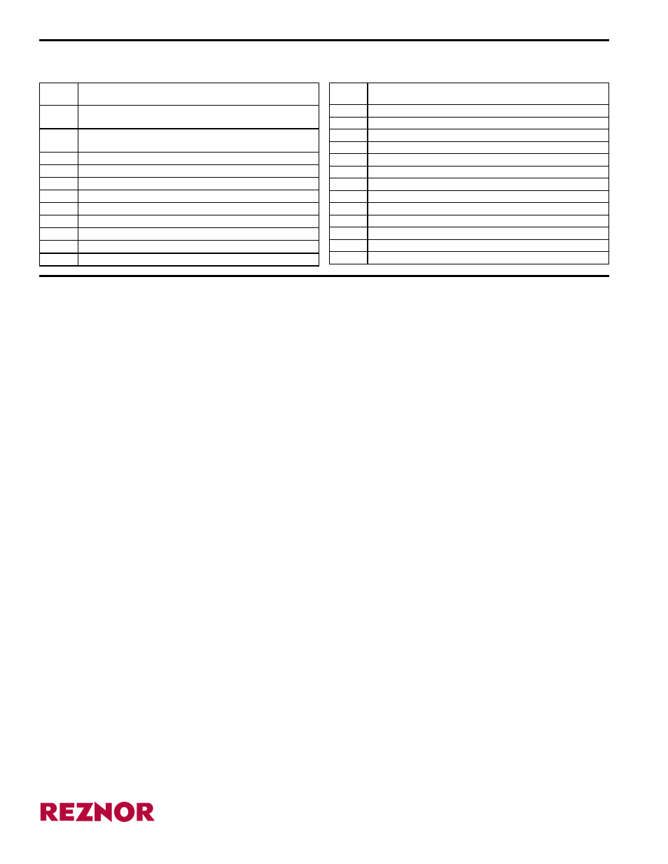
Option Codes for Energy Recovery Module Options listed on the Unit Wiring
Diagram
Option
Code
Description
EM_
Exhaust Fan Drive
EN2
Exhaust Fan Contactor
EN10
Exhaust Fan Starter
ER1A
Energy Recovery Module - MAPS
®
Cabinet A
ER1B
Energy Recovery Module - MAPS
®
Cabinet B
ER1C
Energy Recovery Module - MAPS
®
Cabinet C
SFA_
Supply Fan Motor HP
SFC3
Neutral Pressure Control for SFD1
SFC9
Adjustable Constant Volume Control for SFD1
SFD1
Supply Fan Motor Variable Frequency Drive
SL_
Supply Fan Motor Type
SN2
Supply Fan Contactor
SN10
Supply Fan Starter
Option
Code
Description
AR2K
Outside Air w/3-position damper, Return/Exhaust Air w/3-position
damper (MAPS
®
unit), gravity damper on exhaust outlet
AR2L
100% Outside Air - on/off inlet damper; gravity damper on exhaust
outlet
BCH5
LON Card
BE6
Return Air Temperature & Humidity Sensors
BE28
Dirty Filter Switch
EFA_
Exhaust Fan Motor HP
EFC4
Building Pressure Control for EFD1
EFC7
Proportional to MAPS
®
Control for EFD1
EFC9
Adjustable Constant Volume Control for EFD1
EFD1
Exhaust Fan Motor Variable Frequency Drive
EL_
Exhaust Fan Motor Type
Index
A
B
Belt Tension 6
Adjustable Bypass Air 5
Bypass Air Opening Locations 6
C
Cross Reference of MAPS Models and
D
E
Energy Recovery (enthalpy) Wheel 5, 6
Energy Recovery Wheel (Maintenance) 8
F
H
M
Mating (ER Module to MAPS
®
O
P
R
S
Setting the Supply and Exhaust Fans 7
V
W
®