0 blowers, belts, and drives, Energy recovery (enthalpy) wheel (cont’d) – Reznor MAPS IV Option - Installation - Energy Recovery Module Installation User Manual
Page 6
I-MAPSIII&IV-ER, PN262634R3, page 6
The energy recovery module has both a supply fan and an exhaust fan. The supply fan
blower is matched to the airflow range through the energy recovery wheel and must
be checked after the blower on the MAPS
®
unit is set. (Follow the instructions in Para-
graph 9.0.) The exhaust fan is selected to match the MAPS
®
cabinet size.
Each fan system is equipped with a 1 to 5 HP motor and linked belt drive. Depending
on motor type, motor size, and option selection, control may be by either contactor,
starter, or factory-installed VFD.
8.0 Blowers, Belts,
and Drives
Belts and Belt Tension - The supply and exhaust blower systems are equipped with
Power Twist Plus linked blower belts. The linked belts are designed in sections allow-
ing for easy sizing and adjustment. The belt is sized at the factory for the proper ten-
sion. Check belt tension. Proper belt tension is important to the long life of the belt and
motor. A loose belt will cause wear and slippage. Too much tension will cause exces-
sive motor and blower bearing wear. The belt tension should be checked after the first
24 hours of running at full load and at regular maintenance inspections.
If a linked belt needs tightening, the recommended method of tightening the belt length
is to count the number of links and remove one link for every 24. (A link is made up of
two joining sections of belt. For easier removal of links, turn the belt inside out. But be
sure to turn it back before installing. If a belt is removed or replaced, be sure to align
directional arrows on the belt to the proper drive rotation.)
3/4 (19mm)
Belt Tension
WARNING: All
setscrews and
locking collars must
be tightened before
applying power.
Pulley/Shaft Setscrews -
Wrench torque 110 in-
lb minimum to 130 in-lb
maximum.
Bearing Hub - Socket size
5/16"; Torque 165 in-lbs.
Blower Rotation - Each blower housing is marked for proper rotation. Check blower
rotation with the arrow on the housing. If actual rotation is not correct, interchange the
two wires on the 3-phase supply connections at the terminal block. Do not change load
side wiring.
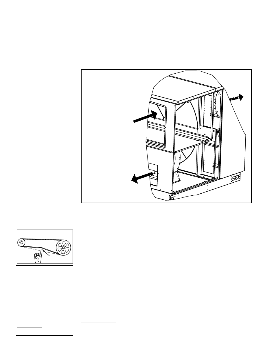
Exhaust
Air
Inlet
Air
Energy
Recovery
Wheel
Inlet
Air Bypass
Exhaust
Air
Bypass
NOTE: Inlet filters
removed for clarity.
(Maps
Unit)
Bypass Air Opening Locations
(Shutter is not shown,
but if required, a shutter
is vertical in each opening.
Panels are removed here
for visibility.)
7.0. Energy
Recovery
(enthalpy)
Wheel (cont’d)
exhausted without going through the wheel. The purpose of the bypass is to increase
the load on the coils for improved coil performance and/or additional reheat capacity.
On some units, the bypass adjustment also allows for a higher supply and exhaust air
volume capacity.
Adjustable shutters allow the width of the bypass openings to be factory set to provide
the percentage of bypass air needed as determined from the specifications provided
on the order. If installation requirements change or if the bypass shutters are mistak-
enly moved, contact the factory or Reznor
®
representative for field adjustment. The
original order information and any changes in specifications must be provided.
NOTE: Option
ER1 energy
recovery modules
manufactured prior
to 4/12 do not have
adjustable shutters on
the bypass openings.