Reznor MAPS IV Option - Installation - Energy Recovery Module Installation User Manual
Page 7
I-MAPSIII&IV-ER, PN262634R3, page 7
Optional Variable Frequency Drive and Controls - When an optional variable fre-
quency drive is ordered, the motor will operate on varying speeds as determined by
the electrical frequency. The energy recovery module may have a factory-installed
VFD on the supply fan and/or the exhaust fan.
Depending on which control was selected, the variable frequency drive on the supply
fan is controlled by neutral pressure or constant volume (adjustable through the IQ
controller).
On the exhaust fan, a VFD may be controlled by building pressure, proportionally
based on the MAPS
®
unit blower, or a constant volume (adjustable through the IQ
controller). For control information, refer to Form CP-MAPS D15/16/17/18.
□
Check that the cabinets have been properly joined and all panels installed. See
Paragraph 4.0.
□
Verify that the electrical connections are all mated correctly and the power supply
wires connected. See Paragraphs 4.0 and 5.0.
□
Check belts, blowers, and setscrews. See Paragraph 8.0.
□
Check the wheel; it should be aligned in the cassette and free to rotate.
Checks before Startup
9.0 Commissioning
and Startup
for Energy
Recovery
Module
□
Setting the Supply and Exhaust Fans - If the energy recovery module is not
equipped with optional variable frequency drives (Options EFD1 and SFD1), it is
recommended that the air balance procedures outlined below be performed.
Checks after Startup
Instructions for MAPS® Unit with an Energy Recovery Module
1. Perform Air Balance Procedure on the MAPS
®
Unit
a) In order to measure airflow without the pressure drop of the energy recovery module, open the coil access door.
(See illustration on page 3.)
b) Energize the MAPS
®
blower system circuit only. Balance the air to the specific air volume requirements for
the application. (If blower speed requires adjustment, follow the instructions in Paragraph 6.6.2 in the MAPS
®
installation manual.)
c) De-energize the MAPS
®
blower system circuit. Close and lock the coil access door.
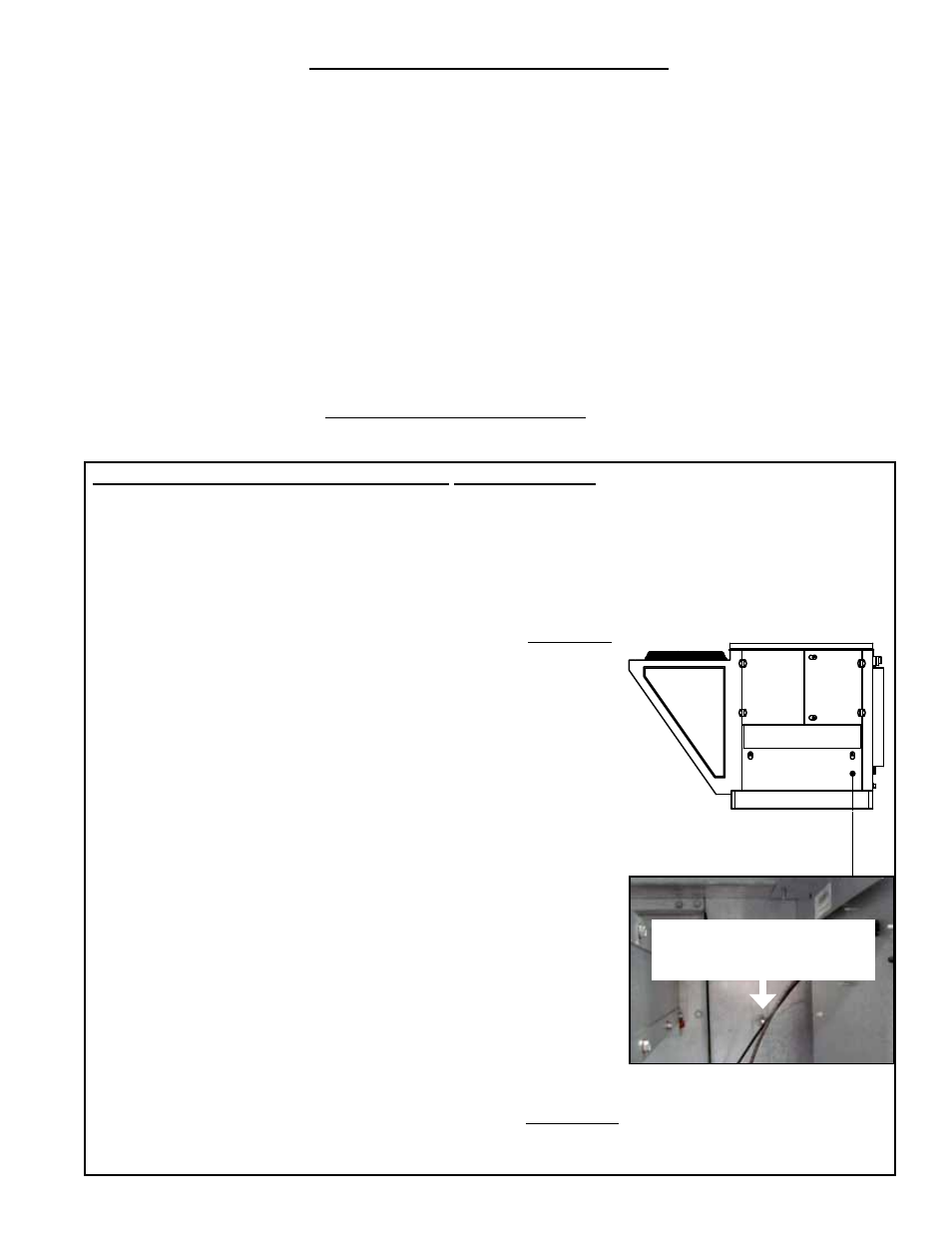
2. Perform Air Balance Procedure on the Energy Recovery Supply Fan
a) On the MAPS
®
unit, open the access panel (heat section access on
units with heat) located below the high voltage control compartment
(see illustration). On the wall next to the blower compartment, locate the
pressure tap. Connect a manometer at the pressure tap.
b) Energize the energy recovery supply blower circuit. If the energy recovery
module has an inlet damper, there will be a delay while the damper opens
and closes the damper end switch that energizes the supply blower.
c) Energize the MAPS
®
blower system circuit.
d) On the manometer, check the pressure. If the measurement is between
0” and -.50” w.c., the supply fan does not need to be adjusted. If the
measurement is not in that range, follow the instructions below:
1) De-energize the energy recovery module and the MAPS
®
unit. (If the
MAPS unit has a gas heat section, turn off the gas.)
2) Loosen belt tension and remove the belt.
3) Loosen the set screw on the side of the pulley.
4) To increase the blower speed, turn the adjustable half of the pulley
inward.
To decrease the blower speed, turn the adjustable half
of the pulley outward. One turn of the pulley will change the speed
8-10%.
5) Tighten the set screw on the flat portion of the pulley shaft.
6) Replace the belt and adjust the belt tension. (See Paragraph 8.0).
7) Energize the system and check the pressure reading. When the
measurement on the manometer is between 0” and -.50” w.c., the
supply fan is set. Disconnect the manometer and close the control panel door.
3. Perform Air Balance procedure on the Energy Recovery Exhaust Fan
The exhaust blower system operates as an independent air system and can be adjusted using standard air balance
procedures with no effect to the MAPS
®
or energy recovery supply air systems.
Tubing
Access
Compressor
Access
High
Voltage
Control
Access
*
Access Panel
To balance the supply fan,
connect the manometer to
this pressure tap.
* On models with gas or
electric heat, this is the heat
section access panel.