Energy recovery (enthalpy) wheel, Frost prevention control dirty filter switch – Reznor MAPS IV Option - Installation - Energy Recovery Module Installation User Manual
Page 5
I-MAPSIII&IV-ER, PN262634R3, page 5
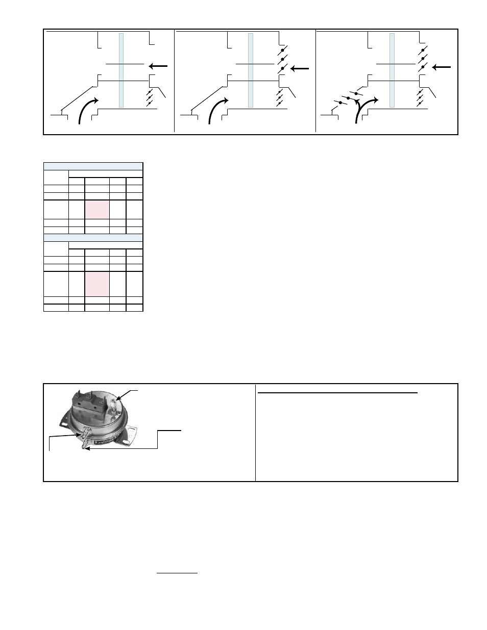
Outside
Air
(MAPS® unit)
Option AR2J
on Energy
Recovery
Module
(Option ER1)
Cabinet
A, B, or C
with Option
ER1
Exhaust Air
(Energy
Recovery
Module)
Outside
Air
(MAPS® unit)
Option AR2L
on Energy
Recovery
Module
(Option ER1)
Cabinet A, B, or C
with Option ER1
Cabinet A, B, or C
with Option ER1
Exhaust Air
(Energy
Recovery
Module)
Outside
Air
(MAPS® unit)
Option AR2K
on Energy
Recovery
Module
(Option ER1)
(Energy
Recovery
Module)
Return /
Exhaust Air
Gravity
Exhaust
Damper
Gravity
Exhaust
Damper
Gravity
Exhaust
Damper
100% Outside Air
with Motorized
Damper in ER
module interlocked
with unit blower
start
Outside Air &
Return Air with
interlocked Motor-
ized Dampers -
requires control
Option GF2
or GF7
Frost Threshold Temperatures (°F)
Indoor Air
R.H. %
Indoor Air Dry Bulb Temperature
70° F
72° F
75° F 80° F
20
-14
-13
-11
-8
30
-3
-2
-1
3
40
5
7 (default
without
Opt BE6)
9
11
50
12
13
15
18
60
18
19
21
26
Frost Threshold Temperatures (°C)
Indoor Air
R.H. %
Indoor Air Dry Bulb Temperature
21° C
22° C
24° C 27° C
20
-26
-25
-24
-22
30
-19
-19
-18
-16
40
-15
-14
(default
without
Opt BE6)
-13
-12
50
-11
-11
-9
-8
60
-8
-7
-6
-3
Frost Prevention
Control
Dirty Filter Switch
Setscrew (on front of switch)
must be manually adjusted
after the system is in
operation.
Negative pressure connection is
toward the "front or top" of the
switch (senses blower side of filters)
Positive pressure
connection is
toward the "back
or bottom" of the
switch (senses air
inlet side of filters)
Instructions for Setting Dirty Filter Switch (located
in the control compartment) - With clean filters in
place; all doors closed (except electrical compartment);
and the blower operating, increase the pressure setting
by adjusting the setscrew on the switch clockwise until
the filter light is energized or the screw is bottomed
out. At that point, adjust the setscrew three full turns
counterclockwise or until the screw is top-ended. At that
setpoint, the filter light will be activated at approximately
50% filter blockage.
All Option ER1 energy recovery modules have a built-in frost prevention sequence.
The frost prevention sequence monitors the outside air temperature, and when the
outside air temperature falls below 7°F (-14°C), the controller implements a wheel
start/stop/jog sequence to prevent frost buildup. Frost will not damage the wheel but
will plug the wheel reducing airflow. The default setpoint of 7°F (-14°C) assumes a
return air design condition with a maximum temperature of 72°F (22°C) at 40% RH as
shown in the table (left). If making a setpoint adjustment, the user must adjust based
on the design conditions shown in the table. Once the outside air is 3°F (2°C) above
the setpoint, wheel operation returns to normal.
If Option BE6 was ordered, in addition to monitoring the outside air temperature, a
factory installed return air temperature and humidity sensor is used to calculate the
frost threshold point and initiates the frost prevention sequence when the outside air
falls below the calculated frost threshold temperature. (Frost threshold temperature is
the point at which frost begins to accumulate on heat exchanger surfaces. It is a func-
tion of both outside air temperature, indoor temperature, and indoor relative humidity.)
With Option BE6, the energy recovery wheel controller monitors the return air tempera-
ture, return air humidity, and outside air conditions and determines the frost threshold
based on the chart (left). Frost prevention is not required until outdoor air temperature
is below the threshold. When the outside air temperature is below the frost threshold,
the controller implements a wheel start/stop/jog sequence to help prevent frost buildup.
Once the outside air temperature is 3°F (2°C) above the calculated frost threshold,
wheel operation returns to normal.
If Option BE28 was ordered, a pressure switch (P/N 105507) senses pressure through
the supply filters. When the setpoint is reached, a signal is sent to the IQ to provide a
“dirty filter alert”.
7.0. Energy
Recovery
(enthalpy)
Wheel
The energy recovery wheel rotates through both the inlet and exhaust airstreams. The
function of the wheel is to transfer both sensible (temperature) and latent (moisture)
energy from one airstream to the air in the other airstream. This allows the energy
recovery module to both cool and dehumidify outdoor makeup air during the cooling
season and heat and humidify outdoor makeup air in the heating season before that
air enters the MAPS
®
unit.
The wheel is rotated by a motor and non-adjustable belt drive. The speed of the rota-
tion is factory set to provide optimum energy transfer.
Bypass Air - Both the inlet and exhaust airstreams have a bypass opening. Depending
on the requirements of the installation, a percentage of filtered outside air is allowed to
enter the MAPS
®
unit without going through the wheel and a percentage of return air is