Reznor REC (Evaporative Cooling) Unit Installation Manual User Manual
Page 7
Form I-REC, P/N 160201 R3, Page 7
Sequence of Operation for Optional Kits:
Applies to: Float and Pump System with Optional Fill and Drain Kit
(Option CT1, CT2, or CT3)
1) Call for cooling.
2) 2-way valve is energized and closes B to A.
3) 3-way valve is energized opening B to C and closing A to C.
4) During no call for cooling, valves return to normal state.
Applies to: AquaSaver Timed Water System with Optional
Freeze Protection (Option CT5)
1) Call for cooling.
2) 3-way valve is energized opening B to C and closing A to C.
3) If outside air temperature drops below freeze protection controller
setting, 3-way valve is de-energized and AquaSaver 24V solenoid valve
remains energized for eight minutes to allow complete system water
drainage.
4) During no call for cooling, 3-way valve returns to normal state.
Evaporative
Cooling
Module
Inlet Water Connection -
1/4compressionfitting to
the float or 1/2 male NPT
fitting for AquaSaver
Overflow Fitting - 3/4 male NPT
tapped with 1/2 female NPT
Drain Fitting -
3/4 male NPT tapped
with 1/2 female NPT
2-Way Solenoid Valve
(normally open)
1/2 female NPT
(A 2-way valve is in
Options CT1, CT2, and
CT3. 2-way valve in
drain does not apply
to AquaSaver freeze
protection Option CT5.)
To Drain
3-Way Solenoid Valve (valve is suitable for a maximum close-off pressure
differential of 25 psi and a system static pressure of 300 psi) - 1/2 NPT,
2-position spring return (normally closed at B port)
(A 3-way valve is in fill and drain kit Options CT1, CT2, CT3,
and freeze protection Option CT5.)
Actuator must be above the valve body when
mounted in horizontal piping.
Roof
Water Inlet
Field-supplied Service Valve
Field-supplied Pressure Regulator (if required)
A
A
B
B
C
= Field-installed Water Piping
Left Side View
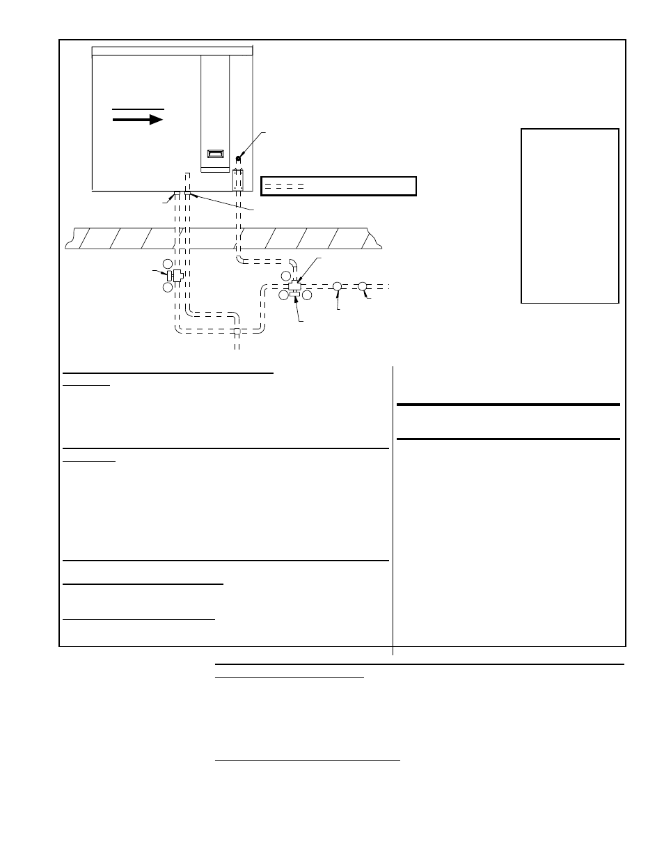
Water Line Connections (See illustration.):
Supply (3-Way Valve) Connections - Connect the water supply line to “B”
(normally closed). Connect the water drain line to “A” (normally open). Con-
nect the middle outlet “C” to supply the water to the cooling module reservoir.
Drain (2-Way Valve) Connections - Connect the drain pipe from the reser-
voir to “B”. Connect the outlet side to “A” and connect into drain lines from
the cooling reservoir and the supply valve.
Electrical Connections (requires black
and white 14-gauge wire) - Refer to Wiring
Diagram provided with the furnace:
WARNING: Risk of electrical shock.
Disconnect the power.
1. Refer to the wiring diagram for terminal
connections. (NOTE: If kit is not ordered with
the system, connections will not be shown on
the diagram. Terminal connections are specific
to each system. Contact the factory for
terminal connections. Be prepared to provide
all model information.)
2. Run field-supplied black wire from the
electrical compartment (terminal on the wiring
diagram) of the evaporative cooling module
and connect to the black wire on both the
3-way and the 2-way valve.
3. Run field-supplied white wire from the
electrical compartment (terminal on the wiring
diagram) of the evaporative cooling module
and connect to the white wire on both the
3-way and the 2-way valve.
NOTE: Follow
instructions
included in the
valve packages
for attaching
valves to the
water line only.
The remainder
of the installation
instructions with
the valves do not
apply to this type
of application.
FIGURE 9 - Water Connections including Optional Fill and
Drain Kit for a Float and Pump Control System and a Freeze
Protection Kit for an AquaSaver Timed Metering System
NOTE: If installing a Size REC360, one fill and drain or freeze protection
kit may be used for both modules if lines are manifolded.
Filling and Adjusting the Water Level in the Reservoir (module equipped with
pump and float controls only) – Turn on the water supply. Check for a good flow.
When the float valve (
FIGURE 6) shuts off the water supply, measure the water depth.
The depth of the water should be approximately 3”. It may be necessary to adjust the
float valve to obtain the proper water level or to free the float valve from obstructions.
To adjust the float valve, simply bend the float valve rod upward to raise the water level
or downward to lower he water level.
Check for Water Leaks - All Modules - The reservoir was water tested but should be
checked again for small leaks. If any leaks are present, dry the reservoir and apply a
field-supplied waterproof silicone sealer around corners and welds.
Proper water flow over the evaporative cooling media is critical to extend the life and
maintain the efficiency of the pads.