0 mechanical (cont’d), 2 water flow controls and connections (cont’d) – Reznor REC (Evaporative Cooling) Unit Installation Manual User Manual
Page 6
Form I-REC, P/N 16021R3, Page 6
3.0 Mechanical
(cont’d)
3.2.3 Inlet Water and Drain Connections
Inlet Water - All Cooling Modules - Install a manual water shutoff upstream of the
inlet, at a convenient non-freezing location, to allow the water supply to be turned on
and off. If necessary, install a bleed line between the manual valve and the cooling
module inlet to allow drainage of the line between the shutoff valve and the cooling
module.
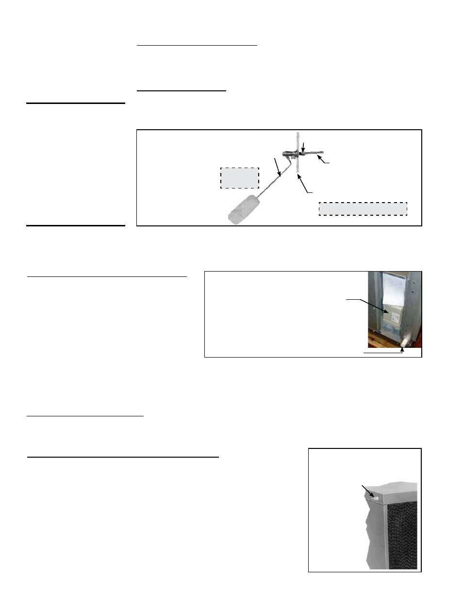
Pump and Float Controls - A float valve (FIGURE 6) maintains the appropriate water
level in the reservoir. Use a field-supplied 1/4” diameter tubing with a compression
nut and tubing ferrule to connect the fresh water supply to the inlet of the float valve.
Place nut and ferrule over tubing and insert tubing into the float valve stem. Tighten
nut securely.
FIGURE 6 -
Connect
Fresh Water
Supply to Inlet
of the Float
Valve (module
with float and
recirculating
pump controls)
Use 1/4” tubing for
fresh water supply.
Simulates Side Panel
Float Valve Rod
Field-supplied Compression
Nut and Tubing Ferrule
Outside the Cabinet
WARNING: Water
reservoir (outdoor
systems) must
be drained and
pump motor turned
off when outside
temperature falls
below 32°F (0°C). DO
NOT operate pump
without water in the
reservoir.
FIGURE 7 -
Electrical Box
(cover removed)
and Water
Connection on
Module with
AquaSaver
Controls
1/2” Supply
Line Connection
Microprocessor
Control Location -
AquaSaver System
AquaSaver Timed Metering Control System - If
the cooling module is equipped with a microproces-
sor timed metering system, connect a 1/2” water line
to the fitting on the side of the cooling module (
FIG-
URE 7).
Due to various water pressures and installation
conditions, the water supply line may bang abruptly
when the solenoid valve in the system closes. This
banging can be minimized by installing a water
hammer arrestor in the supply line. If installing an
An optional automatic fill and drain kit (Option CT1, CT2, or CT3) will automatically release supply water to the cooling
module when a call for cooling is made and will drain all water from the reservoir when the cooling switch is deactivated
or a cooling thermostat is satisfied. Fill and drain kits are field-installed. If installing an optional fill and drain kit, see
FIGURE 9, and follow the instructions that apply. Consult the wiring diagram for electrical connections.
3.2 Water Flow
Controls and
Connections
(cont’d)
Inside
Cabinet
optional water hammer arrestor, select an indoor (above 32°F/0°C) location, either horizontal or vertical, in line with
and as close to the solenoid valve as possible. Follow the manufacturer’s instructions to install and maintain the water
hammer arrestor.
A freeze protection kit is available for a module with a timed control system. It includes a two-way valve and is shipped
separately for field installation. See
FIGURE 9.
Drain and Overflow Connections - All cooling modules are equipped with an overflow and drain fitting. The fittings are
in the cabinet bottom and come complete with a locknut and a sealing gasket. Check these fittings for tightness before
installing the overflow and drain piping. The drain and overflow fitting will accommodate a 3/4” garden hose thread and
is tapped with a 1/2” female pipe thread for iron pipe.
Install bleed
line fitting
(fitting is
shipped in
the bottom
pan of the
evaporative
cooling
module).
FIGURE 8 - Bleed Line
Fitting (float and pump
controls)
Bleed Line Connection (pump and float controls only) – Using the 1/4” I.D. x
1/2” N.P.T. nylon bleed line fitting (shipped in evaporative cooler bottom pan; see
checklist in Paragraph 1.3), thread the fitting into the female adapter on the distri-
bution pipe. The hose barb will protrude from the side of the cabinet (See
FIGURE
8). Attach a field-supplied 1/4” I.D. hose to the barb and run to the nearest drain.
Discharging a quantity of water by “bleed off” will limit the concentration of unde-
sirable minerals in the water being circulated through the cooling module. Miner-
als build up because evaporation only releases “pure water vapor” causing the
concentration of contaminants in the water to increase as the evaporation process
continues to occur. The minerals accumulate on the media, in the water lines, on
the pump, and in the reservoir.
Adequate bleed off is important to maintaining an efficiently operating evaporative
cooling system.