3 supply air discharge, 0 mechanical (cont'd) – Reznor ADFH Unit Installation Manual User Manual
Page 18
Form I-ADF, Page 18
6.0 Mechanical
(cont'd)
6.3 Supply Air
Discharge
6.3.1 Distribution of Makeup Air
Makeup air can be introduced to the building either through distribution ducts or through
controlled pressurization with little or no ductwork. Makeup air should be introduced
and maintained using the lowest possible air velocity. With ductwork distribution, this
is accomplished using a multiplicity of discharge openings over the greatest centerline
distance. When a makeup air system is automatically controlled to maintain a set build-
ing pressure, the entering air will travel naturally toward the relief areas at the perim-
eter walls using the building structure as the distribution ductwork.
Makeup air should enter at the highest point practical. By doing this, the fresh air will
entrain dust laden air at the ceiling and move it toward the point of exhaust. Also, fresh
air directed downward from the roof or ceiling will mix with hot ceiling air resulting in
improved distribution of heat in the building.
Always introduce fresh makeup air so that it moves across the greatest distance within
the room or building before reaching an exhauster.
Sizing and Installation of Distribution Ductwork - Proper sizing of warm air duct-
work is necessary to ensure a satisfactory heating installation. The recognized author-
ity for such information is the Air Conditioning Contractors Association, 2800 Shirling-
ton Road, Suite 300, Arlington, VA 22206 (www.acca.org). A manual covering duct
sizing in detail may be purchased directly from them.
Installing Ducts (See Paragraph 4.2 for duct connection dimensions.):
The type of duct installation depends in part on the type of construction of the
roof (wood joist, steelbar joist, steel truss, pre-cast concrete, etc.) and the ceiling
(hung, flush, etc.).
Rectangular ducts should be constructed of not lighter than No. 26 U.S. gauge gal-
vanized iron or No. 24 B&S gauge aluminum.
All duct sections 24" or wider, and over 48" in length, should be cross-broken on
top and bottom and have seams or angle-iron braces. Joints should be S and drive
strip or locked.
Warm air ducts should not contact masonry walls. Insulate around all air ducts
through masonry walls with not less than 1/2" of insulation.
Insulate all exposed warm air ducts passing through an unheated space with at
least 1/2" thickness of insulation.
Duct Supports - Suspend all ducts securely from adjacent building members. Do
not support ducts from unit duct connections.
Duct Connections - At the heater, use a flexible canvas connection on indoor
units to eliminate vibration transmission. On outdoor installations, the ducts can
be slid over the flange of the heater and then sealed for an airtight and watertight
fit. On duct-to-heater connections, use sheetmetal screws to fasten ducts to the
heater flange. Use stiffening flanges around the perimeter of the duct connections.
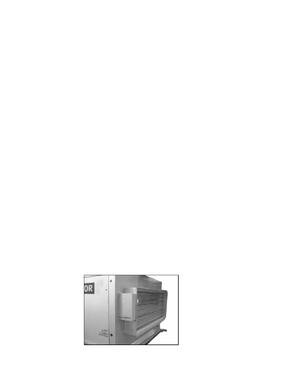
FIGURE 19 - Model
ADF with Horizontal,
Two-Position Discharge
Damper, Option AQ4
The two-position (open/closed) verti-
cal discharge damper
(Option AQ3)
is available on both Model ADF and
ADFH. Discharge dampers are open
when the unit is operating and are
closed when the unit is shut down.
6.3.2 Two-Position
Discharge Dampers,
Option AQ4
A Model ADF unit ordered with Option AQ4 has a factory installed horizontal open/
closed discharge damper. The direct-coupled damper motor is rated for low ambient
temperature and is externally mounted on the control side of the damper frame. The
horizontal damper frame extends 6-5/8" (168mm) beyond the heater duct connection
as illustrated in
FIGURE 19.