Reznor ADFH Unit Installation Manual User Manual
Page 15
Form I-ADF, P/N 131805 R5, Page 15
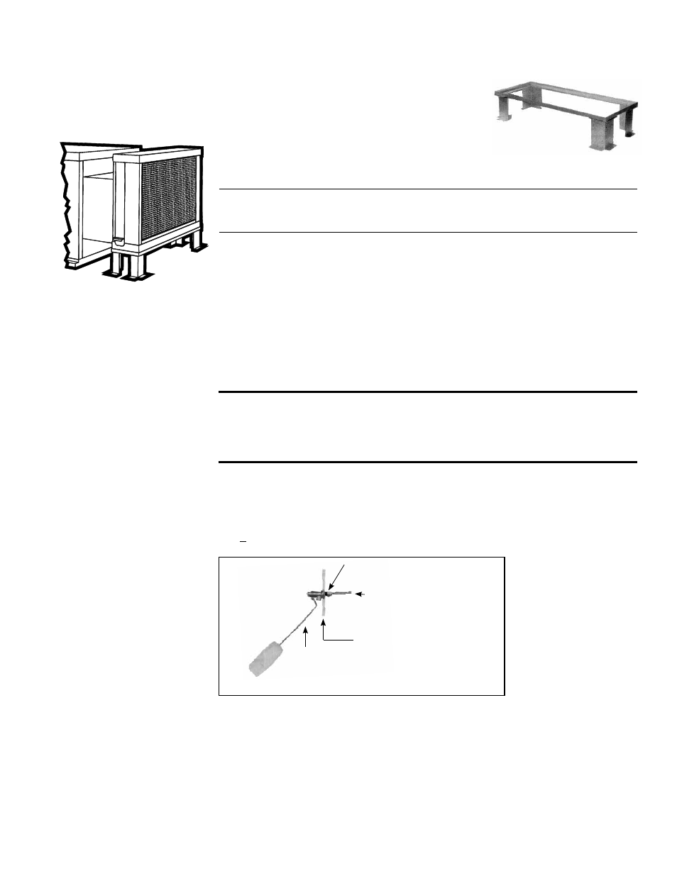
FIGURE 12 - Optional
Evaporative Cooling
Module on an ADF/
ADFH 700 or 1200.
Assembled module is
shipped separately for field
installation.
an adjustable base, and the transition ductwork between the cooling module and the
cabinet. Complete installation instructions including dimensions are packaged with the
evaporative cooling module package.
Included in the cooling module installation
booklet is a preparation checklist. All items
in that checklist should be addressed prior
to beginning installation of the evaporative
cooling module. Four of those items are
listed below.
Make certain the roof or platform is
capable of handling the additional load of a full cooling module reservoir.
Wts of Evaporative Cooling Module w/ Wet Media & Full Reservoir
Module with 12" rigid cellulose media (Option AS4) . 431 lbs (196 kg)
Module with 12" rigid glass fiber media (Option AS8)
514 lbs (233 kg)
Make certain the roof is level and free of debris where the cooling module will be
mounted.
Do not mount directly on soft tar roofs where the legs could sink and tilt the cooling
module. Provide a weather-resistant, solid wood or metal base under the cooling
module support legs.
Make certain that there will be adequate clearance between the bottom of
the reservoir and the roof (or platform) to allow for drain and overflow pipe
connections.
All Sizes - If an optional fill and drain kit is part of the installation, the kit is shipped
separately. Connect the fill and drain kit as illustrated in
FIGURE 14.
Adjustable Leg Height
16" maximum; 9" minimum
Float
Valve
Rod
Compression Nut
and Tubing Ferrule
Use 1/4" Tubing for
Fresh Water Supply
Simulates Cabinet
Side Panel
FIGURE 13 - Connect
Fresh Water Supply to
Inlet of Float Valve
(Inside the
Cabinet)
Evaporative Cooling
Module Water
Connections and
Adjustments
WARNINGS: Water reservoir must be drained and pump motor
turned off when outside temperature falls below 32°F. Pump must
never be operated without water in the reservoir. See Hazard
levels, page 2.
Supply and Drain Water Connections
Float Valve (FIGURE 13) - In a module with pump and float controls, a float valve
maintains the appropriate water level in the reservoir.
Use a field-supplied 1/4" diameter tubing with a compression nut and tubing ferrule to
connect the fresh water supply to the inlet of the float valve. See
FIGURE 13. Place nut
and ferrule over tubing and insert tubing into the float valve stem. Tighten nut securely.
AquaSaver
®
Timed Metering Control System - If the cooling module is equipped
with an optional timed metering system, connect a 1/2" water line to the fitting on the
side of the cooling module.
Due to various water pressures and installation conditions, the water supply line may
bang abruptly when the solenoid valve in the AquaSaver system closes. This banging
can be minimized by installing an optional water hammer arrestor in the supply line. If
installing an optional water hammer arrestor, select an indoor (above 32°F) location,
either horizontal or vertical, in line with and as close to the solenoid valve as possible.
Follow the manufacturer's instructions to install and maintain the water hammer arres-
tor.