0 mechanical (cont'd), 2 unit inlet air (cont'd) – Reznor ADFH Unit Installation Manual User Manual
Page 12
Form I-ADF, Page 12
Installation Instructions
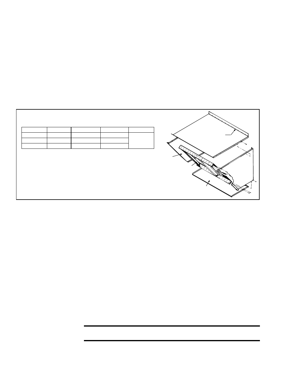
(Refer to Air Hood Assembly Drawing in FIGURE 8B. All screw ends except those
across the bottom should be inside the air hood.)
To avoid possible damage, it is recommended that the outside air hood be installed
after the unit has been placed on the roof. The air hood should be installed before the
heater is operated. Do not install the air hood while the heater or blower is in operation.
1. Install Top Panel - On the air inlet end of the cabinet, remove the row of factory-
installed screws attaching the cabinet top. Slide the air hood top panel underneath
the edge of the cabinet top. The edge of the air hood top panel
must be between
the cabinet top and end panel. Reinsert all of the sheet metal screws.
2. Install Side Panels - Slide the air hood right side panel into the slot between the
cabinet end panel and corner leg. Be sure that the side panel is underneath and
to the inside of the air hood top panel. Attach to the cabinet and the air hood top
using the required number of self-drilling sheet metal screws. Repeat with the left
side panel.
Top Panel
(edge must be
under cabinet top)
Left Side
Panel,
P/N 100217
Right Side Panel,
P/N 100216
Factory-assembled Louver
Assembly including Moisture
Eliminating Louvers
Bottom
Panel
FIGURE 8B - Component P/N's and Assembly Drawing
of Option AS2, Outside Air Hood Without Filters
NOTE: Either a Reznor
®
designed optional air inlet
hood or evaporative cooling
module is required on outdoor
installations to ensure complete
weather resistance and to retain
certification.
3. Install Bottom Panel - Position the air hood bottom panel so that it is to the inside
of the two side panels and above the factory-installed support angle. Attach to both
side panels.
If the bottom panel does not rest tightly against the support angle, follow these
instructions to adjust the position of the support angle:
a) Slightly loosen (do not remove) the support angle screws.
b) Slide the support angle up (holes are slotted) so that it is against the bottom
panel.
c) Tighten the screws.
Attach the support angle to the air hood bottom panel. The bottom panel of the air
hood and the support angle should be tight together; do not draw with the sheet-
metal screws.
4. Install the Louver Assembly - With the intake screen toward the inside of the
hood, position the pre-assembled vertical louver assembly in the inlet opening of
the air hood. Using the remaining sheet metal screws, attach the louver assembly
to the air hood side panels using the holes provided.
6.2.2 Screened
Outside Air Hood
with Filters - Options
AS6, AS7, AS10,
AS12
6.0 Mechanical
(cont'd)
6.2 Unit Inlet Air
(cont'd)
6.2.1 Screened
Outside Air Hood
without Filters
(cont'd)
Size
Top Panel Bottom Panel Louver Assy Side Panels
300
100228
100235
103774
See
illustration
for P/N's.
500
100230
100237
103776
700 & 1200
100232
100239
103778
Screened air hoods are available with a filter rack and 2" disposable filters, 1" or 2"
permanent filters, or 2" disposable pleated filters. Screened air hoods with filters are
shipped factory-assembled for field installation. To avoid possible damage, it is recom-
mended that the outside air hood be installed after the unit is in its permanent location.
The dimensions are shown in
FIGURE 9B.
CAUTION: It is recommended that the inlet to the outside air hood not be
facing into the prevailing wind.
Follow the instructions below to attach the outside air hood to the inlet air end of the
system cabinet.