0 mechanical (cont'd), 2 unit inlet air (cont'd) – Reznor ADFH Unit Installation Manual User Manual
Page 14
Form I-ADF, Page 14
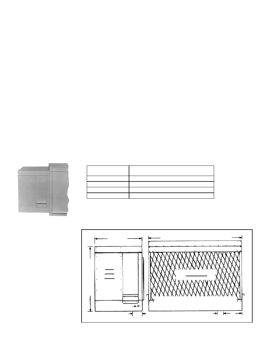
FIGURE 11A - Factory-
installed Evaporative
Cooling Module Option
on Models ADF/ADFH
300 and 500
Evaporative cooling provides excellent comfort cooling at low initial equipment and
installation costs and low operating and maintenance costs. Direct evaporative cooling
works on the principles that water in direct contact with a moving airstream will eventu-
ally evaporate if the droplets have long enough exposure and that the evaporation will
lower the air temperature.
The optional evaporative cooling module is equipped with high efficiency pad media
of either 12" rigid cellulose or 12" rigid glass fiber. 12" media provides 90% efficiency.
Efficiency value is stated at maximum allowable CFM (without the optional moisture
elimination pad) and with an inlet dry bulb temperature of 95
°
F and an inlet wet bulb
temperature of 65
°
F. Evaporative cooling efficiency is a function of inlet temperature
(wet and dry bulbs) and of face velocity through the pads. The stated cooling efficiency
will rise with the decrease of velocity and increase of inlet temperature. Moisture elimi-
nation pads (Option ASA1) may be used on all units but are required on high CFM units
(velocity above 6000 FPM) as listed in the table below.
Model/Size
Moisture Elimination Pad Required Size
on the Evaporative Cooling Module at
ADF/ADFH 300
3200 CFM
ADF/ADFH 500
4500 CFM
ADF/ADFH 700
11200 CFM
ADF/ADFH 1200
11200 CFM
Models ADF/ADFH 300/500 - When ordered with an evaporative cooling option, Sizes
300 and 500 are shipped as a factory-assembled makeup air heating/evaporative cool-
ing system. The module is factory installed including all wiring connections (See
FIG-
URE 11A). Follow the instructions in this section for water connections and water flow
adjustments.
6.2.4 Evaporative
Cooling Module -
Options AS4 and AS8
FIGURE 11B -
Dimensions of optional
evaporative cooling
module factory-
installed on Sizes 300
and 500
23-31/32
(609mm)
Size 300 - 34-1/16 (865mm)
Size 500 - 47-13/16 (1214mm)
32-1/2 (826mm)
Water Connection
(std pump system)
4-1/2 (114mm)
9
(229mm)
2 (51mm)
Rear View
Drain and Overflow Connections
(Std pump control system)
Left
Side
View
3. Re-insert all of the screws across the top of the cabinet.
4. The filter cabinet should be resting on the factory-installed support angle across
the bottom of the cabinet. If the cabinet does not rest tightly against the support
angle, follow these instructions to adjust the position of the support angle:
a) Slightly loosen (do not remove) the support angle screws.
b) Slide the support angle up (holes are slotted) so that it is against the bottom
panel.
c) Tighten the screws.
5. If equipped with an optional dirty filter switch, locate the coil of clear tubing attached
to the dirty filter switch in the electrical compartment. Extend the tubing to the air
entering side of the filter rack. Attach the end of the tubing being careful that it is not
compressed or kinked. (See Paragraph 7.3 for switch details.)
Models ADF/ADFH 700/1200 - The evaporative cooling module for Sizes 700 and
1200 is assembled at the factory and shipped separately for field-connection to the
makeup air system cabinet. The shipped separate option includes the cooling module,
6.0 Mechanical
(cont'd)
6.2 Unit Inlet Air
(cont'd)
6.2.3 Indoor Filter
Cabinet (cont'd)