Étape 1 étape 2, Step 5 – Rev-A-Shelf 6881-39-11-52 User Manual
Page 3
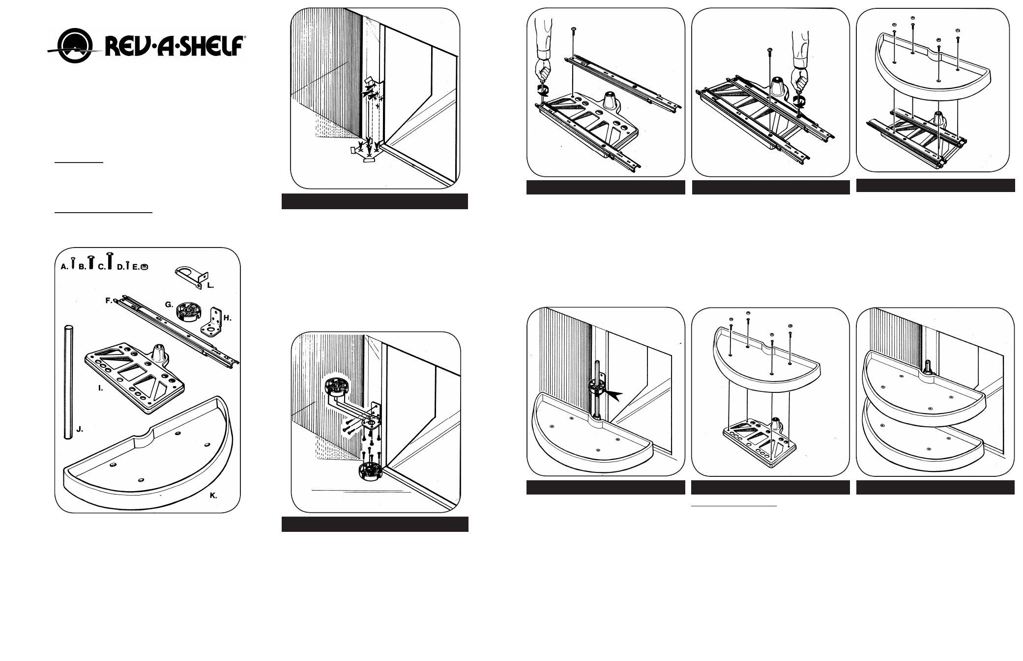
Coller le gabarit en position, verticalement à l’intérieur
de la face du bâti (côté charnière), comme montré sur
l’illustration. Avec une mèche de 1/16 po, percer des
trous guides de 16 mm (5/8 po) de profondeur, à travers
le gabarit, aux 7 endroits identifiés par les flèches. NOTA
– Noter l’emplacement des trous sur le gabarit pour
l’installation de « Rev-A-Tray » (étagère simple).
Mettre la base de mise en position sur les (4) trous
de la base, comme montré, et installer sur le bas du
placard avec quatre (4) vis à bois à tête ovale cruciforme
N° 8 x 3/4 po. Mettre les pattes de support sur les trois
trous guides restant, comme montré et installer dans
le placard avec trois vis à bois à tête ovale cruciforme
N° 8 x 3/4 po. Mettre maintenant l’autre base de mise
en position sur la patte de support avec quatre vis à
métaux à tête cruciforme n° 10 x 1/2 po. NOTA– Bloquer
la vis sur la base de mise en position vers l’ouverture.
NOTA– Le Rev-A-Tray utilise la patte « L ».
ÉTAPE 1
ÉTAPE 2
INSTRUCTIONS POUR LES
ÉTAGÈRES SEMI-CIRCULAIRES DE
838 ET 991 mm (33 ET 39 po)
(ÉLÉMENT DE COIN)
(Illustration du côté gauche seulement)
IMPORTANT – Avant de commencer, il faut se
familiariser avec le contenu du kit, identifier toutes
les pièces, lire attentivement les instructions et
avoir les outils nécessaires avant de commencer.
SERVICE APRÈS-VENTE – Ligne d’aide gratuite
pour répondre à vos questions, les jours de
semaine, pendant les heures d’ouverture :
800-626-1126
IDENTIFICATION DES PIÈCES
A. Vis à bois à tête ovale cruciforme n° 8 x ¾ po
7 néc.
B. Vis à métaux à tête cruciforme ¼ - 20 x 3/4 po
8 néc.
C. Vis à métaux à tête cruciforme ¼ - 20 x 1 po
8 néc.
D. Vis à métaux à tête cruciforme n° 10 x ½ po
4 néc.
E. Embouts en plastiques pour les trous de vis
8 néc.
F. Glissière
4 néc.
G. Base de mise en position
2 néc.
H. Patte de support
1 néc.
I. Support d’étagère
2 néc.
J. Axe de 432 mm (17 po) avec embout
1 néc.
K. Étagère semi-circulaire
2 néc.
L. Patte de support Rev-A-Tray
1 néc.
With top half of slides still all the way
extended, complete slide installation
to 2 remaining threaded holes on shelf
support. Use two (2) more (1 per slide)
1/4-20 x 3/4” Phillips machine screws and
screw them in through the large access
holes in top half of slides (see
illustration).
Place slides on top of shelf support with
this slide toward door opening. Pull top
half of slide all the way out and match
bottom half end holes over threaded
holes on shelf support. Fasten slides to
support using two (2) (1 per slide)
1/4 - 20 x 3/4” Phillips machine screws
(see
illustration).
Take your pivot & slide assembly, match
it over the bottom positioner base
and insert the shaft through the top
positioner base, the pivot and slide
assembly, and into the bottom positioner
base until the shaft bottom (open end)
sets on cabinet bottom. Now using your
screw driver, tighten the set screws on
both positioner bases (arrow points out
top set screw). Be sure to tighten bottom
positioner base set screw (not visible in
illustration).
Pivot Only Assembly: Install Half Moon
tray directly to shelf support using four
(4) 1/4 - 20 x 1” Phillips machine screws.
Then push plastic caps into all 4 tray
holes (illustration shows plastic caps
above screws).
Now slide the pivot assembly on shaft so
it rests on the top positioner base. Your
installation is now complete and should
look like the illustration.
STEP 3
STEP 4
STEP 6
STEP 7
STEP 8
Now match a Half Moon tray over slides
and install it to slides with four (4) 1/4 - 20 x 1”
Phillips machine screws. Illustration shows
the 4 holes for correct installation of tray
to slides. Then push (4) plastic screw cover
caps into tray holes (caps shown over screws
in illustration).
STEP 5