65b65b65bcontinuous packet type field, 66b66b66banalog filter clocks 1,2,3, 67b67b67borientation field – Moog Crossbow NAV440 Series User Manual
Page 84: Configuration fields, Continuous packet type field, Analog filter clocks 1,2,3, Orientation field, Table 59 filter clocks, Table 60 orientation fields, Er to orientation field on
Page 84
NAV440 User Manual
7430‐0131‐01 Rev. F
Continuous Packet Type Field
This is the packet type that is being continually output. The supported packet depends on the model number.
Please refer to
on page for a complete list of the available packet types.
Output Packets (Polled or Continuous)
Analog Filter Clocks 1,2,3
These three fields set hardware low pass filter cutoff frequencies. Each sensor listed is defined in the default factory
tended orientation.
orientation. Users must consider any additional rotation to their in
Table 59 Filter Clocks
Filter Clock
Sensor
analogFilterClock1
Ux, Uz Accel
analogFilterClock2
Uy Accel
analogFilterClock3
Ux, Uy, Uz rate
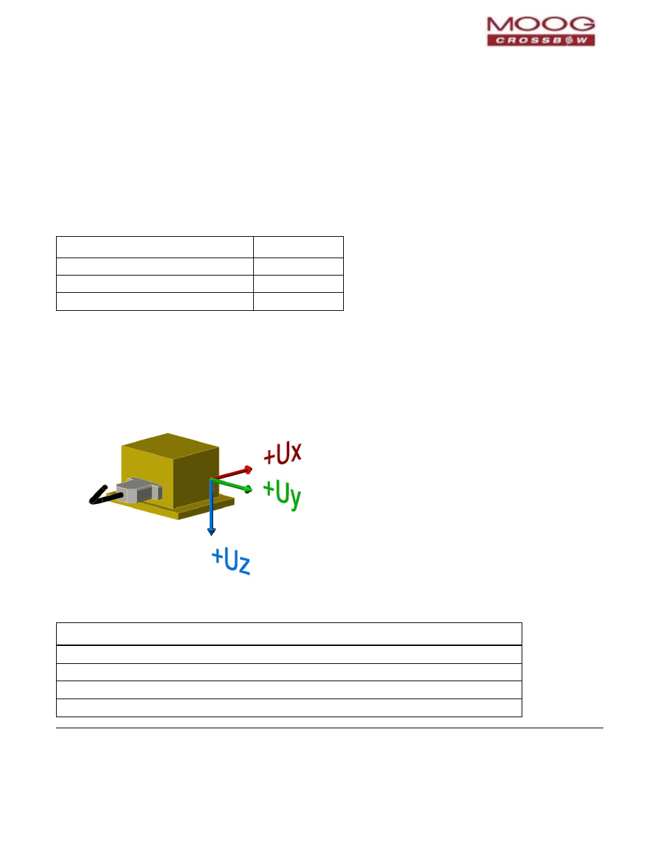
Orientation Field
This field defines the rotation from the factory to user axis sets. This rotation is relative to the default factory
orientation (connector aft, base plate down). The default factory axis set is (Ux, Uy, Uz) defined by the connector
pointing in the –Ux direction and the base plate pointing in the +Uz direction. The user axis set is (X, Y, Z) as defined
by this field. An example of the factory axis set is shown below:
Figure 21 Orientation Fields
Table 60 Orientation Fields
Axis
Bits
Values
X Axis Sign
0
0 = positive, 1 = negative
X Axis
1:2
0 = Ux, 1 = Uy, 2 = Uz, 3 = N/A
Y Axis Sign
3
0 = positive, 1 = negative
Y Axis
4:5
0 = Uy, 1 = Uz, 2 = Ux, 3 = N/A