28b28b28bfunctional block diagram, Functional block diagram, Figure 1 440 series hardware block diagram – Moog Crossbow NAV440 Series User Manual
Page 21: Figure 2 440 series software block diagram, Softw, Figure 2below, 100hz sig, Gnals are, Figure 2, t, C ne
NAV440 User Manual
7430‐0131‐01 Rev. F
Page 21
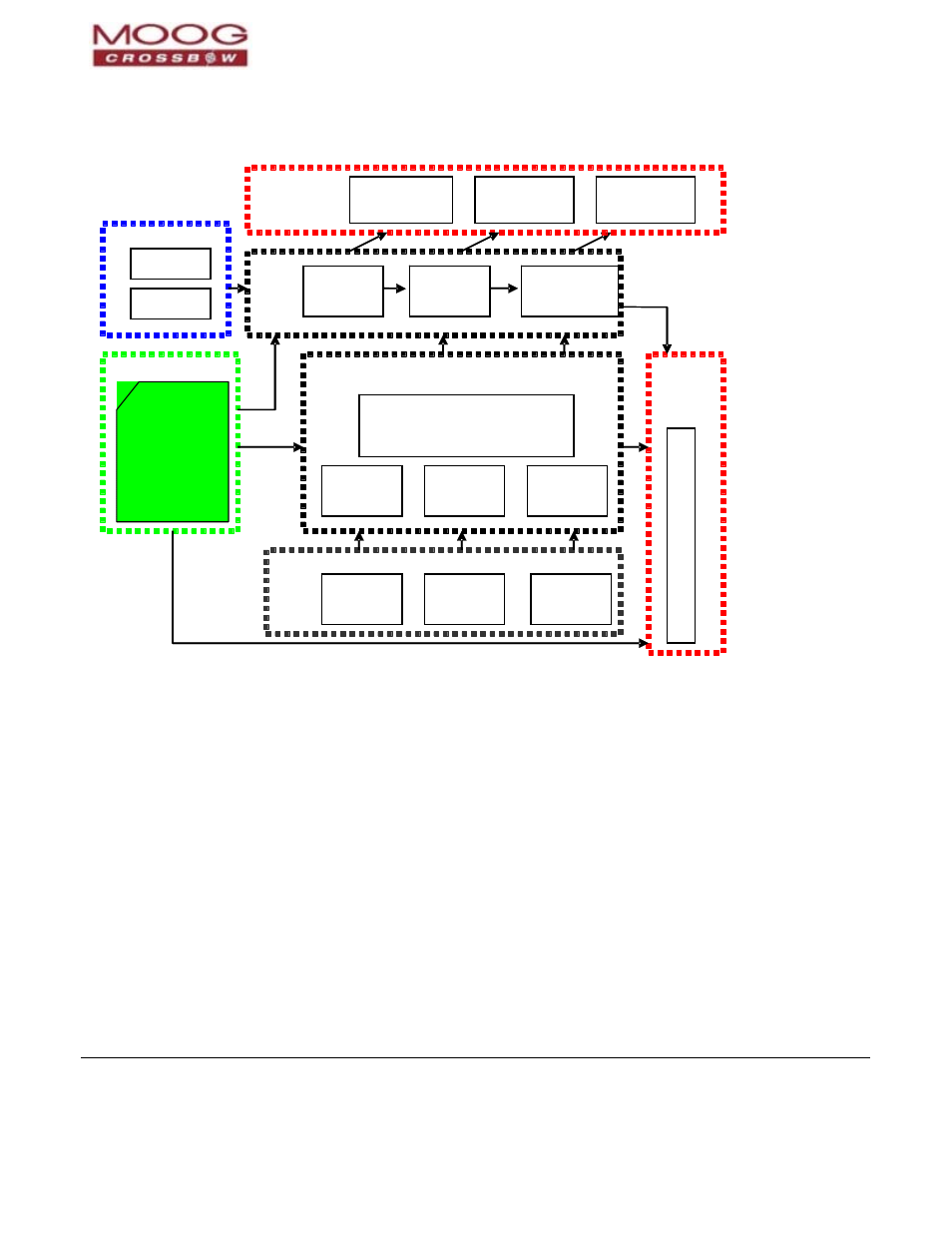
Figure 2 440 Series Software Block Diagram
X / Y / Z Body
Accelerometers
6
-
DOF Sensor Cluster
Sensor
Calibration
Axes Rotation
GPS Data
Internal/External
Kalman Filter and DynamicState Model
Integration to 100 Hz
Velocity, GPS
Position Output
Hard/Soft Iron
Calibration
UseMags
X / Y / Z
Magnetometers
NAV/AHRS only
IMU -
Scaled Packets
(S0,S1,S2)
All Units
NAV/AHRS/VG/IMU
Gravity Reference
Turn Rate
(Internal
Computation)
Free Integrate
TurnSwitch
Threshold
UseGPS
Stationary Yaw
Lock
X / Y / Z Body
Rates
100Hz
Signal
Proc.
Chain
Extended Kalman Filter (EKF)
Drift Correction Module
VG/AHRS – Angle
Packets
(A0,A1,A2)
NAV/AHRS/VG
NAV - Nav Packets
(N0,N1)
NAV/AHRS/VG
Integration to
Attitude
Unit Settings & Profile*
Communication Settings
Axes Orientation
LowPass Filtering
Free Integrate
UseGPS
UseMags
TurnSwitch
Threshold
DynamicMotion
Restart On Overange
Dynamic Motion
Programmable BIT Alerts
Aiding Sensors
Built In Test
& Status
Data
Availabe to
User
Measurement
Data Available to
User (Fixed Rate
or Polled)
Status Packet (T0)
Functional Block Diagram
Figure 3below illustrates the unit setting and profile block, which configures the algorithm to user and application
specific needs. This feature is one of the more powerful features in the 440 architecture; it allows the 440 Series to
work in a wide range of commercial applications by setting specific functions.