S31 – bit mapped connect detect register, S32 – pulse dial make timer, S33 – pulse dial break timer – Maxim Integrated 73M2901CE AT Command User Manual
Page 32: S34 – pulse dial inter-digit timer, S35 – cadence a min on time of dial tone, S36 – cadence a max on time of dial tone, S37 – cadence a min off time of dial tone
73M2901CE AT Command User Guide
UG_2901CE_027
32
Rev.
2.0
4.4.32
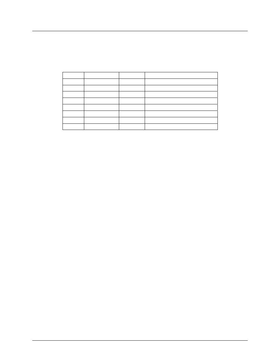
S31 – Bit Mapped Connect Detect Register
(Default = 00h)
The value in this register indicates the DCE speed of the last established connection. This is a read only
register. The default value is 0 until connection is established.
Bit
Decimal Value Hex Value
Mode
0
1
$01
Successful 4-Wire Connection. (T)
1
2
$02
Successful Bell 202 Connection
2
4
$04
Successful V.22 bis Connection.
3
8
$08
Successful V.22 Connection.
4
16
$10
Successful Bell 212 Connection.
5
32
$20
Successful Bell 103 Connection.
6
64
$40
Successful V.21 Connection.
7
128
$80
Successful V.23 Connection.
Note: All bits are zero until a successful connection has been established (carrier detect valid, data mode
active). Then the appropriate bit will be set.
4.4.33
S32 – Pulse Dial Make Timer
(Default = 39)
Duration of Pulse Make time in ms. Range is 1 to 211.
4.4.34
S33 – Pulse Dial Break Timer
(Default = 61)
Duration of Pulse Break time in ms. Range is 1 to 211.
4.4.35
S34 – Pulse Dial Inter-digit Timer
(Default = 75)
Duration of Pulse Inter-digit time interval in units of 10ms. Range is 1 to 211.
4.4.36
S35 – Cadence A Min On Time of Dial Tone
(Default = 0)
The value of this register sets the duration of the primary cadence minimum dial tone ON time in units of
40ms.
4.4.37
S36 – Cadence A Max On Time of Dial Tone
(Default = 0)
The value of this register sets the duration of the primary cadence maximum dial tone ON time in units of
40ms.
4.4.38
S37 – Cadence A Min Off Time of Dial Tone
(Default = 0)
The value of this register sets the duration of the primary cadence minimum dial tone OFF time in units of
40ms.