S22 – bit mapped register, 24 s23 – busy detect cadence count, S23 – busy detect cadence count – Maxim Integrated 73M2901CE AT Command User Manual
Page 28
73M2901CE AT Command User Guide
UG_2901CE_027
28
Rev.
2.0
4.4.23
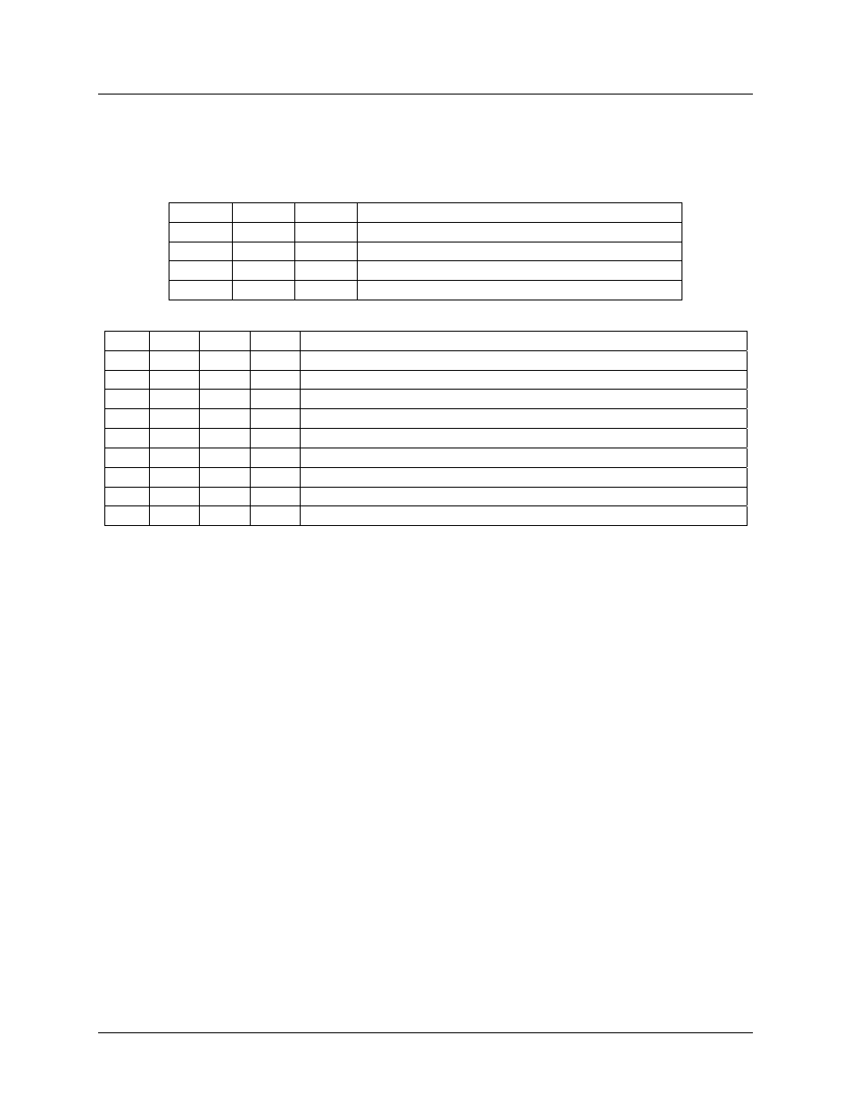
S22 – Bit Mapped Register
(Default = 36h)
Register S22 reflects the status of certain options. Register S22 is a bit mapped register whose bits are
defined as follows:
Bit 2
Bit 1
Bit 0
Function: Synchronous/Asynchronous Control
0
0
0
Y0 Asynchronous Mode
0
0
1
Y1 Synchronous Mode
1
0
0
Y4 Quasi-Synchronous Mode
1
1
0
Y6 Asynchronous with speed buffering (Default)
Bit 6
Bit 5
Bit 4
Bit 3
Function: Select Result Code Set
0
0
0
1
X0 Enable Result Codes 0-4.
0
0
0
0
X1 Enable Result Codes 0-5, 10.
0
0
1
0
X2 Enable Result Codes 0-6, 10.
0
1
0
0
X3 Enable Result Codes 0-5, 7, 10.
0
1
1
0
X4 Enable Result Codes 0-7, 10. (Default)
1
0
0
0
X5 Enable Result Codes 0-5, 10, and detect BUSY at OFF HOOK.
1
0
1
0
X6 Enable Result Codes 0-6, 10, and detect BUSY at OFF HOOK.
1
1
0
0
X7 Enable Result Codes 0-5, 7, 10, and detect BUSY at OFF HOOK.
1
1
1
0
X8 Enable Result Codes 0-7, 10, and detect BUSY at OFF HOOK.
Result Code 0 = OK
Result Code 1 = CONNECT
Result Code 2 = RING
Result Code 3 = NO CARRIER
Result Code 4 = ERROR
Result Code 5 = CONNECT 1200
Result Code 6 = NO DIALTONE
Result Code 7 = BUSY
Result Code 8 = NO ANSWER (if @ dial modifier is used and quiet answer is not detected within S7)
Result Code 9 = CONNECT 0600
Result Code 10 = CONNECT 2400
Result Code 11 = CONNECT 4800
Result Code 12 = CONNECT 9600
Result Code 13 = CONNECT 7200
Result Code 14 = LINE-IN-USE
Result Code 22 = CONNECT 75/1200
Result Code 23 = CONNECT 1200/75
bit 7 0 = Pulse dialing make/break ratio = 39/61 (U.S.) (Default).
1 = Pulse dialing make/break ratio = 33/67 (U.K., Hong Kong).
This bit has an effect only when S32 or S33 are set to zero.
4.4.24
S23 – Busy Detect Cadence Count
(Default = 3)
Defines how many busy cadence cycles before sending the busy result code.