Out of production – LAARS Mighty Max HH (Sizes 320M - 400M) - Installation, Operation and Maintenance Instructions User Manual
Page 9
Mighty Max Hydronic Boiler
Page 9
tubes. Boilers installed in violation of the foregoing
may void the warranty.
2.7.5 Combined Space Heating/Potable
Water Heating Systems
When using the Mighty Max boiler as a source
of heat for a combined space heating/potable water
heating system, be sure to follow the instructions of
the space heating system.
Do not use water piping, fittings, valves, pumps,
and any other components which are not compatible
with potable water.
Do not connect the heater, which will be used to
supply potable water, to any heating system or
components previously used with a nonpotable water
heating system.
Do not add boiler treatment or any chemicals to
the heating system piping, since the piping contains
water for potable use.
Do not use solder containing lead in the potable
water lines.
Some jurisdictions may require a backflow
preventer in the cold water line. In such cases,
pressure relief valve may discharge water due to
expansion. An expansion tank approved for potable
water will eliminate this condition. Follow the
manufacturer's instructions for installation of the
expansion tank.
2.8 Piping of System to Boiler
1.
Be sure to provide gate valves at the inlet and
outlet to the boiler so it can be readily isolated
for service.
2.
The pressure relief valve installed in the tapped
opening provided in the outlet header must be
piped, but not fastened, to a drain or floor sink.
The drain pipe must be the same size as the valve
outlet and must pitch downward from the valve. If
the PRV supplied with the boiler is not factory
installed, install it in the front header consistent
with the ANSI/ASME Boiler and Pressure Vessel
Code, Section IV. Pay special attention to relief
valve settings in installations where the boiler is
located on the ground floor of a tall building, or
where the operating temperature of the boiler is
above 210°F (99°C). In both instances, the static
pressure of the system is elevated and could cause
the relief valve to leak and bring considerable raw
water into the system. Where no special setting of
the relief valve is ordered, the factory will furnish
a 75 psi (511.5 kPa) setting. Never reduce the
relief valve opening. If necessary, install the relief
valve in a Tee immediately past the boiler outlet.
3.
Provide a boiler installed above radiation level
with a low water cutoff device either as part of
the boiler or at the time of boiler installation (see
Figure 7).
4.
Install manual and/or automatic bleeding devices
at high points in the system to eliminate air.
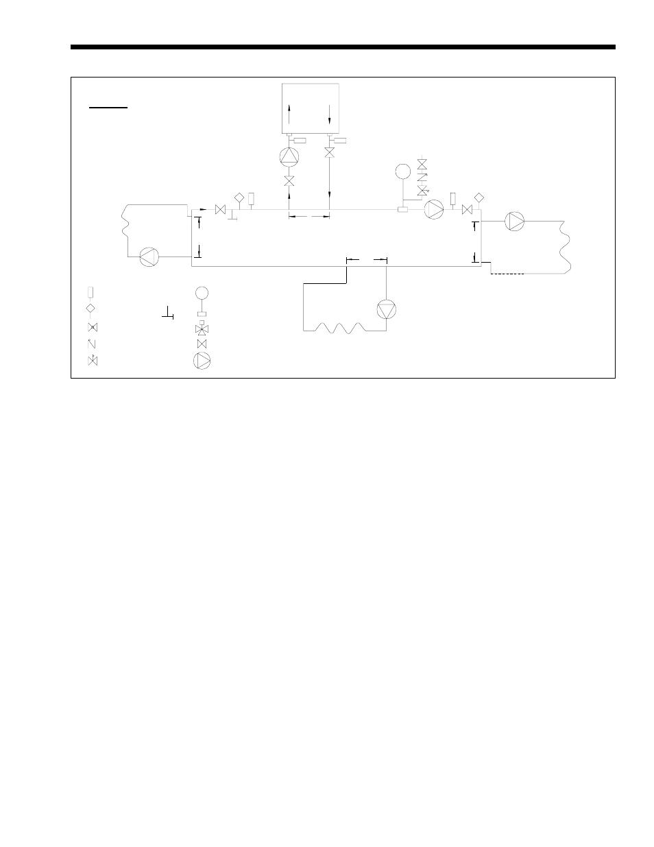
Figure 5. Primary-Secondary Plumbing.
Boiler Circulation
Pump
Cold Water
Make-Up
System Pump
12"
Max.
12"
Max.
12"
Max.
12"
Max.
Thermometer
Temperature
Sensor
Globe Valve
Check Valve
Pressure Reducing Valve
w/Fast Fill Bypass
Expansion Tank
with Air Scoop and
Auto Air Vent
3-Way Valve
Valve
Pump
LEGEND:
Boiler circuit piping must be equal to or larger
than boiler water connection size.
Boiler circulation pump sized for flow through
boiler.
Dotted devices indicate alternate locations.
WARNING: This drawing shows suggested
piping configuraiton and valving. Check with
local codes and ordinances for additional
requirements.
Purge
Valve
OUT OF
PRODUCTION