Out of production – LAARS Mighty Max HH (Sizes 320M - 400M) - Installation, Operation and Maintenance Instructions User Manual
Page 7
Mighty Max Hydronic Boiler
Page 7
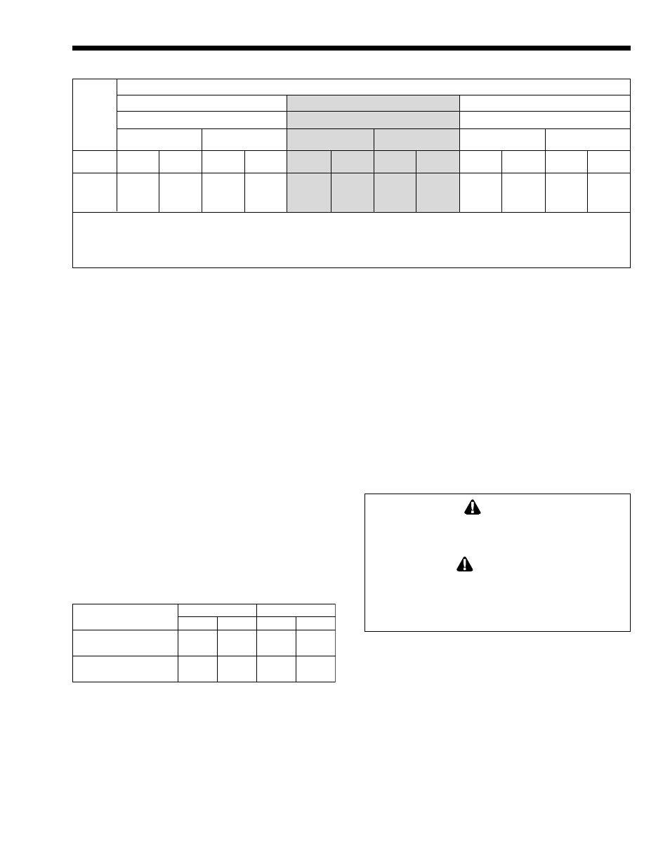
Notes: 1. These numbers are based on 1/2 inch (13mm) water column pressure drop.
2. Check supply pressure and local code requirements before proceeding with work.
3. Pipe fittings must be considered when determining gas pipe sizing.
Table 3. Natural Gas and Propane, Pipe Size Requirements.
Distance from Gas Meter or Last Stage Regulator
0-100 feet
100-200 feet
200-300 feet
0-30m
30-60m
60-90m
Natural
Propane
Natural
Propane
Natural
Propane
Size
in.
mm
in.
mm
in.
mm
in.
mm
in.
mm
in.
mm
320M
1.25
32
1.25
32
1.50
38
1.25
32
1.50
38
1.50
38
400M
1.25
32
1.25
32
1.50
38
1.25
32
2.00
51
1.50
38
3.
The figures in Table 3 should be used to size the
gas piping from the gas meter to the boiler.
Check local codes for BTU/h capacity required.
4.
Install a sediment trap (drip leg) ahead of the gas
controls (see Figure 4). Fit the trap with a
threaded cap which can be removed for cleaning.
5.
When required by code, install a second manual
gas shutoff valve. Do not remove manual shutoff
valve supplied with the boiler.
6.
Disconnect the boiler and its individual shutoff
valve from the gas supply piping system during
pressure testing of the system at pressures higher
than 1/2 psi (3.5 kPa). Isolate the boiler from the
gas supply piping system by closing its
individual manual gas shutoff valve during any
pressure testing of the gas supply piping system
at test pressures equal to or less than 1/2 psi
(3.5 kPa).
7.
Gas supply pressures to the boiler are listed in
Table 4.
Supply Pressure
Water Column
Natural Gas
Propane Gas
in.
mm
in.
mm
Minimum
5
127
9
229
Maximum
9
229
14
356
Table 4. Gas Supply Pressure Requirements.
NOTE: The boiler and all other gas appliances
sharing the boiler gas supply line must be firing at
maximum capacity to properly measure the inlet
supply pressure. Low gas pressure could be an
indication of an undersize gas meter and/or
obstructed gas supply line.
8.
Do not exceed the maximum inlet gas pressures
specified. Excessive pressure will result in
damage to the heater's gas controls. The
minimum pressures specified are for gas input
adjustment.
9.
The correct differential gas pressure is stamped
on the rating plate. The regulator is preset at the
factory, but may need adjustment for altitude per
Section 3.
10. Before operating the heater, test the complete gas
supply system and all connections for leaks using
a soap solution.
CAUTION
Since some leak test solutions (including soap and
water) may cause corrosion or stress cracking,
rinse the piping with water after testing.
ATTENTION
Comme certaines solutions qui testent les fuites (y
compris le savon et l’eau) peuvent causer de la
corrosion ou des fissures sous stress, rincez les
tuyaux avec de l’eau après les tests.
2.7 Water System Requirements
2.7.1 Flow Requirements
The Model HH boilers must have continuous
flow through the heat exchanger when firing for
proper operation. The system pump must be capable
of developing sufficient pressure to overcome the
resistance of the boiler plus the entire circulating
system at the designated flow (see Table 5). The
temperature rise across the boiler should never exceed
20°F (11°C). Minimum inlet water temperature is
120°F (49°C).
OUT OF
PRODUCTION