Out of production – LAARS Mighty Max HH (Sizes 320M - 400M) - Installation, Operation and Maintenance Instructions User Manual
Page 10
Page 10
LAARS Heating Systems
Install a correctly sized expansion or
compression tank with suitable air charger and
tank drainer, as appropriate.
5.
Support the weight of all water and gas piping by
suitable hangers or floor stands.
6.
Check piping diagrams with local applicable
plumbing, heating and building safety codes.
2.9 Filling The System
1.
Ensure the system is fully connected. Close all
bleeding devices and open make-up water valve.
Allow system to fill slowly.
2.
If make-up water pump is employed, adjust
pressure switch on pumping system to provide a
minimum of 12 psi (81.8 kPa) at the highest
point in the heating loop.
3.
If a water pressure regulator is provided on the
make-up water line, adjust the pressure regulator
to provide at least 12 psi (81.8 kPa) at the
highest point in the heating loop.
4.
Open bleeding devices on all radiation units at
the high points in the piping throughout the
system, unless automatic air bleeders are
provided at such points.
5.
Run system circulating pump for a minimum of
30 minutes with the boiler shut off.
6.
Open all strainers in the circulating system,
check flow switch operation, and check for
debris.
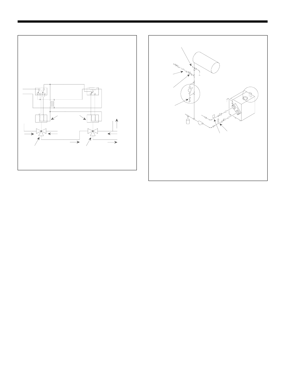
3-Way Valve No. 1
Change-Over
(Heating and Cooling)
3-Way Valve No. 2
To By-Pass
Both Heater and
Chiller
To
System
From
System
By-Pass
To Boiler
and
Chiller
From
Boiler
Valve Motors
2-Pos
3-Wire - 24V
115/24V
Transformer
DPDT Manual or Automatic
Change-Over Switch
DPDT - Set at Change-Over
Temperature
Clock Timer
Auto-Resetting
Set at 15 Minute SPDT
Suggested Wiring Diagram For
Tempering System Water at
Changeover From Heating To Cooling
Figure 6. Boiler-Chiller Installation.
From
Chiller
7.
Recheck all air bleeders as described in Step 4
above.
8.
Check liquid level in expansion tank. With the
system full of water and under normal operating
pressure, the level of water in the expansion tank
should not exceed 1/4 of the total, with the
balance filled with air.
9.
Start up boiler according to procedure described
in Section 3.1. Operate the entire system,
including the pump, boiler, and radiation units
for one (1) hour.
10. Recheck the water level in the expansion tank. If
the water level exceeds 1/4 of the volume of the
expansion tank, open the tank drainer and drain
to that level.
11. Shut down the entire system and vent all
radiation units and high points in the system
piping as described in Step 4 above.
12. Close make-up water valve and check strainer in
pressure reducing valve for sediment or debris
from the make-up water line. Reopen make-up
water valve.
13. Check gauge for correct water pressure and also
check water level in the system. If the height
indicated above the boiler insures that water is at
the highest point in the circulating loop, then the
system is ready for operation.
Make-Up
Water
Supply
Check
Valve
Pressure
Reducing
Valve
Blow Down
Valve
Expansion
Tank
To Drain
Method 1
To
Drain
Method 2
To
System
Strainer
Pump
Thermometer
Temperature
and Pressure
Gauge
NOTES: Select Method 1 or 2 when using low water cutoff accessory:
1. Under Method 1, the low water cutoff is furnished by Laars and
shipped as a separate item for fieldinstallation.
2. Under Method 2, electronic low water cutoff isinstalled, wired and
tested on boiler in Laars factory.
3. Preferred locaiton of system pump is shown. Compression tank must
always be on suction side of pump.
Figure 7. Boiler Piping.
Air Changer
and Tank
Drainer
OUT OF
PRODUCTION