Out of production – LAARS Mighty Max HH (Sizes 320M - 400M) - Installation, Operation and Maintenance Instructions User Manual
Page 18
Page 18
LAARS Heating Systems
SECTION 3.
Operation
WARNING
Do not use this appliance if any part has been
under water. Immediately call a qualified service
technician to replace the appliance.
AVERTISSEMENT
N’utilisez pas cet appareil s’il a été en partie
submergé. Appelez immédiatement un technicien
qualifié pour remplacer l’appareil.
3.1 Start Up Requirements
Lighting: Safe lighting and other performance
criteria were met with the gas manifold and control
assembly provided on the boiler when it underwent
tests specified in ANSI Z21.13 Standard.
Before placing the boiler in operation, check the
automatic safety shutoff devices. Once the boiler is
connected to the gas piping and after all of the
requirements in Section 2 have been met, follow this
procedure:
1.
Before beginning the tests, make sure the main
manual gas valve, and any other boiler firing
valves, are in the OFF position.
NOTE: The gas valve is turned off as follows:
2.
Press in gas control knob slightly and turn
clockwise to OFF. Knob cannot be turned unless
it is pushed in slightly. Do not force it.
3.
Make sure the power switch on the boiler is in
the ON position. Reset all safety devices (high
limit, pressure switch, Low-Water-Cutoff, etc.).
4.
Normal Operating Sequence
When the circulation pump is running, the boiler
will turn itself on and off in response to the water
temperature. When the water cools below the set
temperature, the following sequence occurs:
a.
The aquastat powers the ignition control.
b.
The ignition control turns on the
combustion fan. After about a 15 second
pre-ignition purge, while the fan clears the
combustion chamber, the igniter is turned
on. The igniter takes about 25 seconds to
heat up. You can see a glow through the
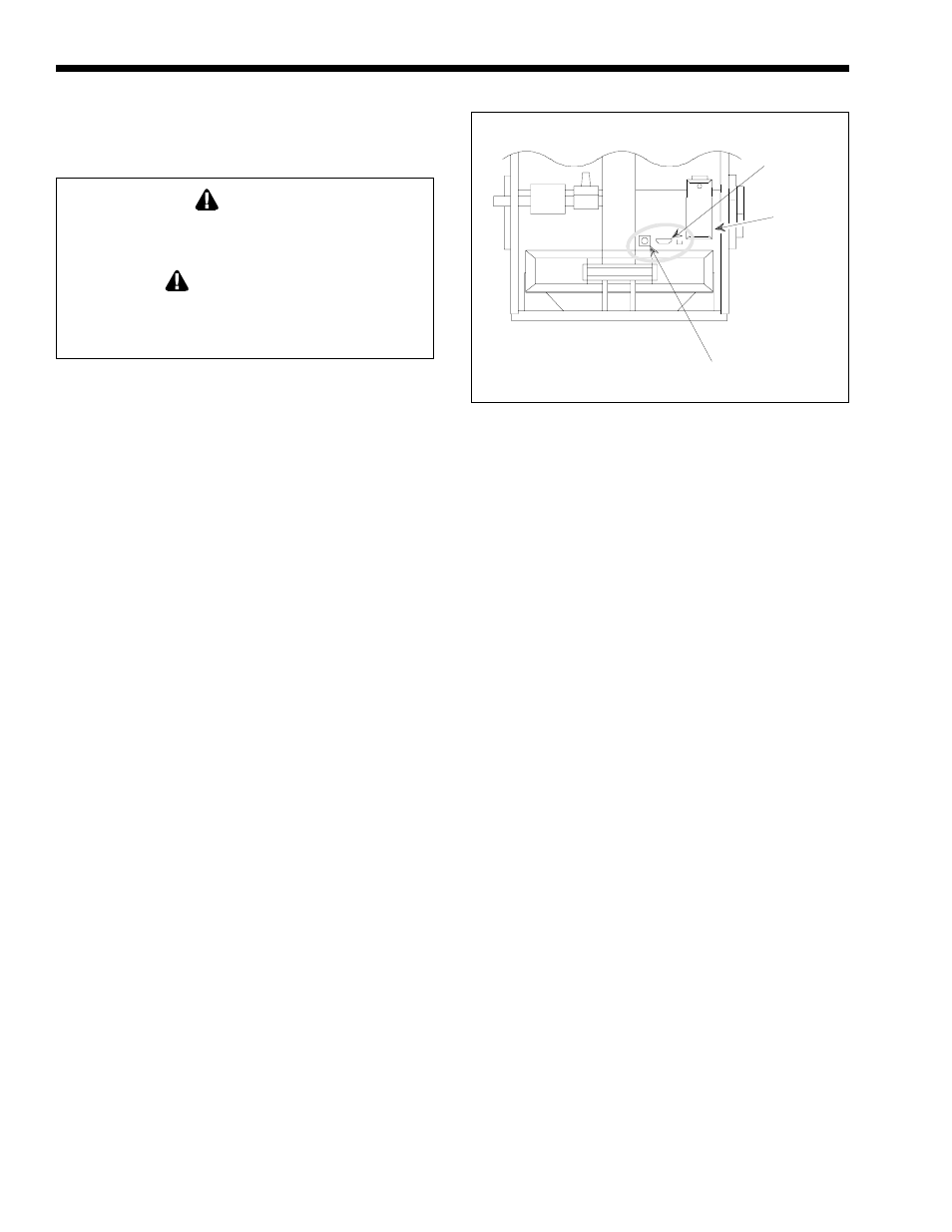
view port (see Figure 13).
NOTE: The manual gas valve must be ON for the burner
to ignite. This valve is turned ON as follows:
c.
Turn counterclockwise to ON.
d.
When the igniter is hot, the ignition control
turns on the gas valve and the burner
ignites. You can see the burner flame
through the view port (see Figure 13).
Junction
Box
Front View of Boiler
NOTE: Sight glass
location may vary.
Figure 13. Periodic Flame Observation.
Igniter
Sight Glass
For Flame Observation
e.
The boiler operates until the aquastat senses
that the water is hot enough, and the burner
shuts off. The combustion fan runs for
about one minute to blow all combustion
products out of the boiler.
If the igniter fails to ignite the burner in step 3
(for example, if there is air in the gas line), the ignition
control shuts off the gas valve after a few seconds of
operation. The purge and ignition sequence is
automatically repeated. If there is no ignition in three
tries, the ignition control “locks out” until the problem
is corrected. Contact a qualified service technician.
3.1 Critères de démarrage
Éclairage: L’éclairage ainsi que d’autres critères
de sureté ont été verifiés avec les commandes de gaz
installées sur la chaudière au cours des test effectués
qui sont recommandés dans le ANSI Z21.13 Standard.
Avant de mettre la chaudière en marche, vérifiez
le dispositif de sûreté d’arrêt automatique. Une fois
que la chaudière est branchée à la tuyauterie de gaz et
une fois que toutes les conditions de la Section 2 ont
été remplies, suivez cette démarche :
1.
Avant de commencer les tests, assurez-vous que
la valve manuelle principale de gaz et toutes les
autres valves de démarrage de la chaudière sont
en position OFF (arrêt).
NOTA: La valve de gaz est arrêtée comme suit :
2.
Appuyez légèrement sur le bouton de contrôle de
gaz et tournez-le dans le sens des aiguilles d’une
montre à OFF. Le bouton ne peut pas tourner à
moins d’appuyer légèrement. Ne pas forcer.
3.
Assurez-vous que l’interrupteur sur la chaudière
est en position ON (marche). Réglez tous les
dispositifs de sécurité (limite haute, interrupteur
de pression, arrêt-eau-minimum, etc.).
4.
Séquence normale d’opération. Quand la pompe
OUT OF
PRODUCTION