Wiring, Warning, Page 9 laars sequencing controls s8 & s8ext – LAARS S8Ext - Installation Manual User Manual
Page 9: Wiring the power (terminals 1, 2), Wiring the sensors, Lo hi unit1 stages lo hi unit2 stages
Page 9
LAARS Sequencing Controls S8 & S8EXT
WIRING
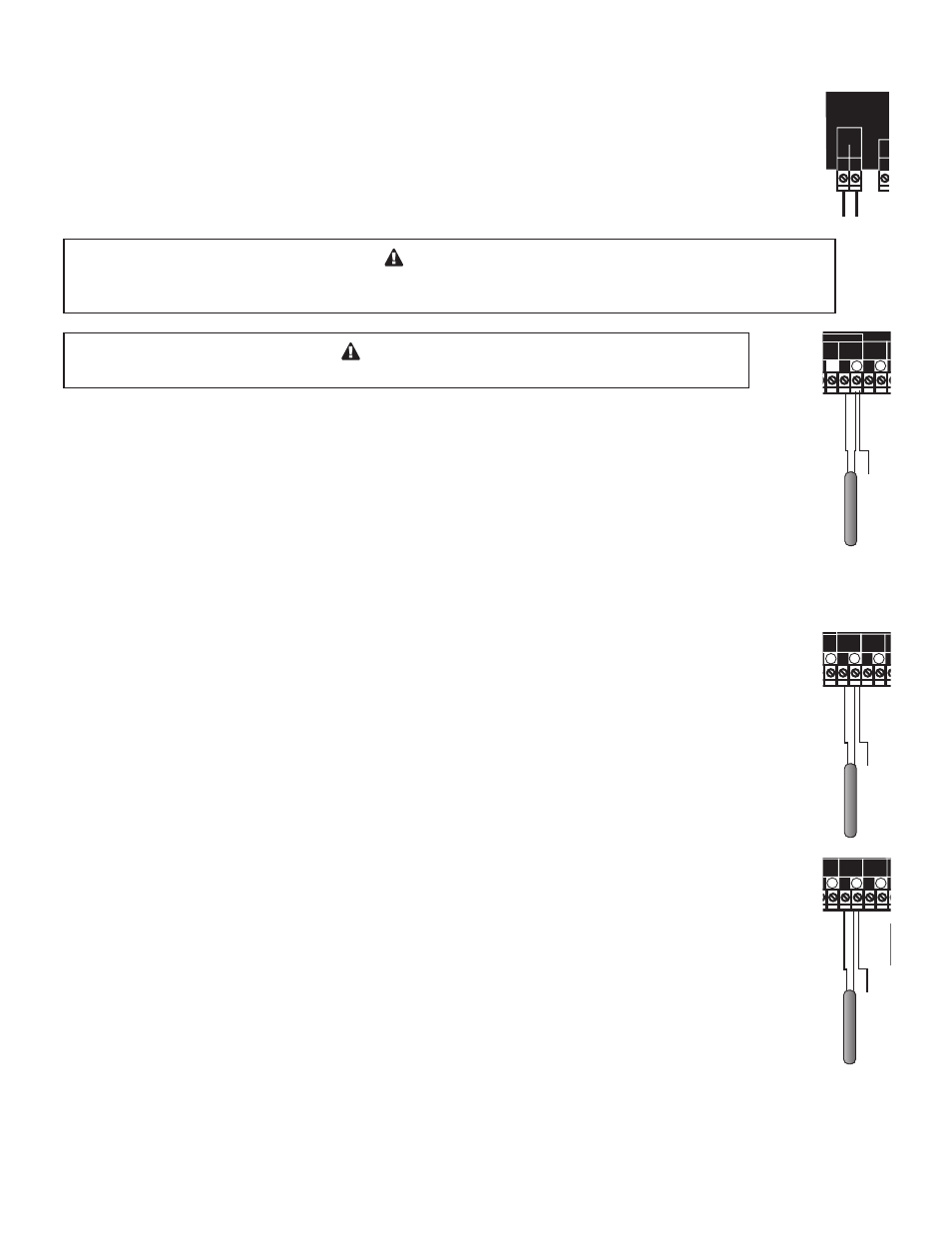
WIRING THE POWER (TERMINALS 1, 2)
• Bring the 120VAC 60Hz power wires through the bottom Knockout of the enclosure.
• Class 1 voltages must enter the enclosure through a different opening from any Class 2 voltage wiring.
• Connect the hot line to terminal marked L.
• Connect the neutral line to the terminal marked N.
WARNING
Class 1 voltages must enter the enclosure through a different opening from any Class 2 voltage
wiring. Laars recommends installing a surge suppressor on the power source to the S8.
Line
Neutral
120VAC
Power Source
Sensor Shiled
Use Copper Conductors Only.
CAUTION:
Risk of Electric Shock.
PWR
L N
1 2
SENSORS MUST BE GOLD SERIES
SYSTEM
3
DHW
PUMP
5
Stage A
7
Stage B
9
Stage C
11
13
Stage E
15
Stage F
17
Stage D
6
8
10
12
14
16
18
RS485
4
Stage G
19
Stage H
21
OUTDOOR
TEMP
27
29
31
DHW
33
SHUTDOWN
/SETBACK
35
RETURN
TEMP
20
22
28
30
32
34
36
25
26
PRESS
+ -
37
38
PROVE
SYSTEM
TEMP
PROGRAM
RUN
OUTPUT RATING: 6 AMP RESISTIVE, 1 AMP PILOT DUTY PER OUTPUT AT 120VAC.
23 24
COMB.
AIR
DO NOT APPLY ANY VOLTAGE TO INPUT TERMINALS
Outdoor Sensor
Prove Dry Contact
Sensor Shiled
System Sensor
Sensor Shiled
Return Sensor
Shutdown Dry Contact
Sensor Shiled
DHW Sensor
Lo Hi
Unit1
Stages
Unit1
Pump
Lo Hi
Unit2
Stages
Unit2
Pump
System
Pump
DHW
Pump
Comb.
Air
Damper
Use Copper Conductors Only.
CAUTION:
Risk of Electric Shock.
PWR
L N
1 2
SENSORS MUST BE GOLD SERIES
SYSTEM
3
DHW
PUMP
5
Stage A
7
Stage B
9
Stage C
11
13
Stage E
15
Stage F
17
Stage D
6
8
10
12
14
16
18
RS485
4
Stage G
19
Stage H
21
OUTDOOR
TEMP
27
29
31
DHW
33
SHUTDOWN
/SETBACK
35
RETURN
TEMP
20
22
28
30
32
34
36
25
26
PRESS
+ -
37
38
PROVE
SYSTEM
TEMP
PROGRAM
RUN
OUTPUT RATING: 6 AMP RESISTIVE, 1 AMP PILOT DUTY PER OUTPUT AT 120VAC.
23 24
COMB.
AIR
DO NOT APPLY ANY VOLTAGE TO INPUT TERMINALS
Setback Dry Contact
Lo Hi
Unit1
Stages
Lo Hi
Unit2
Stages
WARNING
Connect the shield at the control terminal end and cut the shield wire at the sensor end.
Line
Neutral
120VAC
Power Source
Sensor Shiled
Use Copper Conductors Only.
CAUTION:
Risk of Electric Shock.
PWR
L N
1 2
SENSORS MUST BE GOLD SERIES
SYSTEM
3
DHW
PUMP
5
Stage A
7
Stage B
9
Stage C
11
13
Stage E
15
Stage F
17
Stage D
6
8
10
12
14
16
18
RS485
4
Stage G
19
Stage H
21
OUTDOOR
TEMP
27
29
31
DHW
33
SHUTDOWN
/SETBACK
35
RETURN
TEMP
20
22
28
30
32
34
36
25
26
PRESS
+ -
37
38
PROVE
SYSTEM
TEMP
PROGRAM
RUN
OUTPUT RATING: 6 AMP RESISTIVE, 1 AMP PILOT DUTY PER OUTPUT AT 120VAC.
23 24
COMB.
AIR
DO NOT APPLY ANY VOLTAGE TO INPUT TERMINALS
Outdoor Sensor
Prove Dry Contact
Sensor Shiled
System Sensor
Sensor Shiled
Return Sensor
Shutdown Dry Contact
Sensor Shiled
DHW Sensor
Lo Hi
Unit1
Stages
Unit1
Pump
Lo Hi
Unit2
Stages
Unit2
Pump
System
Pump
DHW
Pump
Comb.
Air
Damper
Use Copper Conductors Only.
CAUTION:
Risk of Electric Shock.
PWR
L N
1 2
SENSORS MUST BE GOLD SERIES
SYSTEM
3
DHW
PUMP
5
Stage A
7
Stage B
9
Stage C
11
13
Stage E
15
Stage F
17
Stage D
6
8
10
12
14
16
18
RS485
4
Stage G
19
Stage H
21
OUTDOOR
TEMP
27
29
31
DHW
33
SHUTDOWN
/SETBACK
35
RETURN
TEMP
20
22
28
30
32
34
36
25
26
PRESS
+ -
37
38
PROVE
SYSTEM
TEMP
PROGRAM
RUN
OUTPUT RATING: 6 AMP RESISTIVE, 1 AMP PILOT DUTY PER OUTPUT AT 120VAC.
23 24
COMB.
AIR
DO NOT APPLY ANY VOLTAGE TO INPUT TERMINALS
Use Copper Conductors Only.
CAUTION:
Risk of Electric Shock.
PWR
L N
1 2
SENSORS MUST BE GOLD SERIES
SYSTEM
3
DHW
PUMP
5
Stage A
7
Stage B
9
Stage C
11
13
Stage E
15
Stage F
17
Stage D
6
8
10
12
14
16
18
RS485
4
Stage G
19
Stage H
21
OUTDOOR
TEMP
27
29
31
DHW
33
SHUTDOWN
/SETBACK
35
RETURN
TEMP
20
22
28
30
32
34
36
25
26
PRESS
+ -
37
38
PROVE
SYSTEM
TEMP
PROGRAM
RUN
OUTPUT RATING: 6 AMP RESISTIVE, 1 AMP PILOT DUTY PER OUTPUT AT 120VAC.
23 24
COMB.
AIR
DO NOT APPLY ANY VOLTAGE TO INPUT TERMINALS
Setback Dry Contact
Lo Hi
Unit1
Stages
Lo Hi
Unit2
Stages
WIRING THE SENSORS
SYSTEM TEMPERATURE SENSOR WIRING (TERMINALS 27, 28)
• A S8 must be connected to a temperature sensor located in the common header.
• The S8 is designed to be connected to a temperature sensor (CA002400 or equivalent) for immersion in a
3/8ID well (CA002500 or equivalent). Contact the factory for additional temperature sensor options.
• Temperature sensor wires can be extended up to 500’ by splicing shielded 2-
conductor cable (Belden #8760 or equivalent).
• Temperature sensors have no polarity. Connect the two wires from the
sensor to the S8 terminals marked SYSTEM TEMP 27, 28.
• Connect the sensor shield to the circled terminal 28 with one of the sensor wires.
OUTDOOR SENSOR WIRING (TERMINALS 29, 30)
• When Outdoor Reset is selected, the S8 will vary the system Set Point based on outdoor temperature.
• Whether in Set Point or Outdoor Reset modes, the outdoor sensor can be used as an Outdoor Cutoff. In
heating, the S8 will disable all Boilers when the outdoor temperature is above the adjustable Outdoor
Cutoff temperature. However, in cooling it will disable the units when the outdoor temperature is below
the Outdoor Cutoff. This feature will automatically be activated when an outdoor sensor is connected.
• For an outdoor sensor use a Laars outdoor sensor (CA002400 or equivalent).
• The sensor wires can be extended up to 500’ using shielded 2-conductor cable (Belden #8760 or equivalent).
• Temperature sensors have no polarity. Connect the wires from the outdoor
sensor to the S8 terminals marked OUTDOOR TEMP - 29, 30.
• Connect the shield to the circled terminal 30 with one of the sensor wires.
Line
Neutral
120VAC
Power Source
Sensor Shiled
Use Copper Conductors Only.
CAUTION:
Risk of Electric Shock.
PWR
L N
1 2
SENSORS MUST BE GOLD SERIES
SYSTEM
3
DHW
PUMP
5
Stage A
7
Stage B
9
Stage C
11
13
Stage E
15
Stage F
17
Stage D
6
8
10
12
14
16
18
RS485
4
Stage G
19
Stage H
21
OUTDOOR
TEMP
27
29
31
DHW
33
SHUTDOWN
/SETBACK
35
RETURN
TEMP
20
22
28
30
32
34
36
25
26
PRESS
+ -
37
38
PROVE
SYSTEM
TEMP
PROGRAM
RUN
OUTPUT RATING: 6 AMP RESISTIVE, 1 AMP PILOT DUTY PER OUTPUT AT 120VAC.
23 24
COMB.
AIR
DO NOT APPLY ANY VOLTAGE TO INPUT TERMINALS
Outdoor Sensor
Prove Dry Contact
Sensor Shiled
System Sensor
Sensor Shiled
Return Sensor
Shutdown Dry Contact
Sensor Shiled
DHW Sensor
Lo Hi
Unit1
Stages
Unit1
Pump
Lo Hi
Unit2
Stages
Unit2
Pump
System
Pump
DHW
Pump
Comb.
Air
Damper
Use Copper Conductors Only.
CAUTION:
Risk of Electric Shock.
PWR
L N
1 2
SENSORS MUST BE GOLD SERIES
SYSTEM
3
DHW
PUMP
5
Stage A
7
Stage B
9
Stage C
11
13
Stage E
15
Stage F
17
Stage D
6
8
10
12
14
16
18
RS485
4
Stage G
19
Stage H
21
OUTDOOR
TEMP
27
29
31
DHW
33
SHUTDOWN
/SETBACK
35
RETURN
TEMP
20
22
28
30
32
34
36
25
26
PRESS
+ -
37
38
PROVE
SYSTEM
TEMP
PROGRAM
RUN
OUTPUT RATING: 6 AMP RESISTIVE, 1 AMP PILOT DUTY PER OUTPUT AT 120VAC.
23 24
COMB.
AIR
DO NOT APPLY ANY VOLTAGE TO INPUT TERMINALS
Use Copper Conductors Only.
CAUTION:
Risk of Electric Shock.
PWR
L N
1 2
SENSORS MUST BE GOLD SERIES
SYSTEM
3
DHW
PUMP
5
Stage A
7
Stage B
9
Stage C
11
13
Stage E
15
Stage F
17
Stage D
6
8
10
12
14
16
18
RS485
4
Stage G
19
Stage H
21
OUTDOOR
TEMP
27
29
31
DHW
33
SHUTDOWN
/SETBACK
35
RETURN
TEMP
20
22
28
30
32
34
36
25
26
PRESS
+ -
37
38
PROVE
SYSTEM
TEMP
PROGRAM
RUN
OUTPUT RATING: 6 AMP RESISTIVE, 1 AMP PILOT DUTY PER OUTPUT AT 120VAC.
23 24
COMB.
AIR
DO NOT APPLY ANY VOLTAGE TO INPUT TERMINALS
Setback Dry Contact
Lo Hi
Unit1
Stages
Lo Hi
Unit2
Stages
RETURN SENSOR WIRING (TERMINALS 31, 32) OPTIONAL (AVAILABLE IN HEATING ONLY)
• If the Return Sensor is connected, must be purchased separately, the S8 will recognize
it and alternate its temperature on the display with the Target temperature. If the Return
is below the Minimum Return, the S8 will sequence stages based on the Return Sensor,
Minimum Return, Calculated Target, and the actual System Temperature.
• The Return on the S8 is designed to be connected to a temperature sensor that can be purchased
separately (CA002400 or equivalent) for immersion in a 3/8ID well (CA002500 or equivalent).
• The sensor wires can be extended up to 500’ using shielded 2-conductor cable (Belden #8760 or equivalent).
• Temperature sensors have no polarity. Connect the wires from the outdoor
sensor to the S8 terminals marked OUTDOOR TEMP - 31, 32.
• Connect the shield to the circled terminal 32 with one of the sensor wires.
Line
Neutral
120VAC
Power Source
Sensor Shiled
Use Copper Conductors Only.
CAUTION:
Risk of Electric Shock.
PWR
L N
1 2
SENSORS MUST BE GOLD SERIES
SYSTEM
3
DHW
PUMP
5
Stage A
7
Stage B
9
Stage C
11
13
Stage E
15
Stage F
17
Stage D
6
8
10
12
14
16
18
RS485
4
Stage G
19
Stage H
21
OUTDOOR
TEMP
27
29
31
DHW
33
SHUTDOWN
/SETBACK
35
RETURN
TEMP
20
22
28
30
32
34
36
25
26
PRESS
+ -
37
38
PROVE
SYSTEM
TEMP
PROGRAM
RUN
OUTPUT RATING: 6 AMP RESISTIVE, 1 AMP PILOT DUTY PER OUTPUT AT 120VAC.
23 24
COMB.
AIR
DO NOT APPLY ANY VOLTAGE TO INPUT TERMINALS
Outdoor Sensor
Prove Dry Contact
Sensor Shiled
System Sensor
Sensor Shiled
Return Sensor
Shutdown Dry Contact
Sensor Shiled
DHW Sensor
Lo Hi
Unit1
Stages
Unit1
Pump
Lo Hi
Unit2
Stages
Unit2
Pump
System
Pump
DHW
Pump
Comb.
Air
Damper
Use Copper Conductors Only.
CAUTION:
Risk of Electric Shock.
PWR
L N
1 2
SENSORS MUST BE GOLD SERIES
SYSTEM
3
DHW
PUMP
5
Stage A
7
Stage B
9
Stage C
11
13
Stage E
15
Stage F
17
Stage D
6
8
10
12
14
16
18
RS485
4
Stage G
19
Stage H
21
OUTDOOR
TEMP
27
29
31
DHW
33
SHUTDOWN
/SETBACK
35
RETURN
TEMP
20
22
28
30
32
34
36
25
26
PRESS
+ -
37
38
PROVE
SYSTEM
TEMP
PROGRAM
RUN
OUTPUT RATING: 6 AMP RESISTIVE, 1 AMP PILOT DUTY PER OUTPUT AT 120VAC.
23 24
COMB.
AIR
DO NOT APPLY ANY VOLTAGE TO INPUT TERMINALS
Use Copper Conductors Only.
CAUTION:
Risk of Electric Shock.
PWR
L N
1 2
SENSORS MUST BE GOLD SERIES
SYSTEM
3
DHW
PUMP
5
Stage A
7
Stage B
9
Stage C
11
13
Stage E
15
Stage F
17
Stage D
6
8
10
12
14
16
18
RS485
4
Stage G
19
Stage H
21
OUTDOOR
TEMP
27
29
31
DHW
33
SHUTDOWN
/SETBACK
35
RETURN
TEMP
20
22
28
30
32
34
36
25
26
PRESS
+ -
37
38
PROVE
SYSTEM
TEMP
PROGRAM
RUN
OUTPUT RATING: 6 AMP RESISTIVE, 1 AMP PILOT DUTY PER OUTPUT AT 120VAC.
23 24
COMB.
AIR
DO NOT APPLY ANY VOLTAGE TO INPUT TERMINALS
Setback Dry Contact
Lo Hi
Unit1
Stages
Lo Hi
Unit2
Stages