Warning, Wiring the shutdown (terminals 35, 36), Wiring the setback (terminals 35, 36) – LAARS S8Ext - Installation Manual User Manual
Page 10: Wiring the prove (terminals 37, 38), Wiring the system output (terminals 19, 20), Lo hi unit1 stages lo hi unit2 stages
Page 10
LAARS Heating Systems
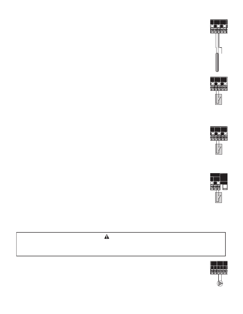
WIRING THE DOMESTIC HOT WATER (DHW) SENSOR (TERMINALS 33, 34)
• DHW can be used to raise system Set Point to 200°F or Maximum Target, whichever is lower. DHW Piping
concept must be selected in the Startup Menu to determine the DHW Priority options.
• DHW Call terminals can be either a dry contact N.O. or a temperature sensor that can be purchased separately
(CA002400 or equivalent) for immersion in a 3/8ID well (CA002500 or equivalent).
• If dry contact, wire an aquastat or other controls to provide closure on the DHW terminals.
• The sensor wires can be extended up to 500’ using shielded 2-conductor cable (Belden #8760 or equivalent).
• Temperature sensors have no polarity. Connect the wires from the DHW sensor to the S8 terminals marked
DHW - 33, 34.
• Connect the shield to the circled terminal 34 with one of the sensor wires.
Line
Neutral
120VAC
Power Source
Sensor Shiled
Use Copper Conductors Only.
CAUTION:
Risk of Electric Shock.
PWR
L N
1 2
SENSORS MUST BE GOLD SERIES
SYSTEM
3
DHW
PUMP
5
Stage A
7
Stage B
9
Stage C
11
13
Stage E
15
Stage F
17
Stage D
6
8
10
12
14
16
18
RS485
4
Stage G
19
Stage H
21
OUTDOOR
TEMP
27
29
31
DHW
33
SHUTDOWN
/SETBACK
35
RETURN
TEMP
20
22
28
30
32
34
36
25
26
PRESS
+ -
37
38
PROVE
SYSTEM
TEMP
PROGRAM
RUN
OUTPUT RATING: 6 AMP RESISTIVE, 1 AMP PILOT DUTY PER OUTPUT AT 120VAC.
23 24
COMB.
AIR
DO NOT APPLY ANY VOLTAGE TO INPUT TERMINALS
Outdoor Sensor
Prove Dry Contact
Sensor Shiled
System Sensor
Sensor Shiled
Return Sensor
Shutdown Dry Contact
Sensor Shiled
DHW Sensor
Lo Hi
Unit1
Stages
Unit1
Pump
Lo Hi
Unit2
Stages
Unit2
Pump
System
Pump
DHW
Pump
Comb.
Air
Damper
Use Copper Conductors Only.
CAUTION:
Risk of Electric Shock.
PWR
L N
1 2
SENSORS MUST BE GOLD SERIES
SYSTEM
3
DHW
PUMP
5
Stage A
7
Stage B
9
Stage C
11
13
Stage E
15
Stage F
17
Stage D
6
8
10
12
14
16
18
RS485
4
Stage G
19
Stage H
21
OUTDOOR
TEMP
27
29
31
DHW
33
SHUTDOWN
/SETBACK
35
RETURN
TEMP
20
22
28
30
32
34
36
25
26
PRESS
+ -
37
38
PROVE
SYSTEM
TEMP
PROGRAM
RUN
OUTPUT RATING: 6 AMP RESISTIVE, 1 AMP PILOT DUTY PER OUTPUT AT 120VAC.
23 24
COMB.
AIR
DO NOT APPLY ANY VOLTAGE TO INPUT TERMINALS
Setback Dry Contact
Lo Hi
Unit1
Stages
Lo Hi
Unit2
Stages
WIRING THE SHUTDOWN (TERMINALS 35, 36)
• This feature will only be available when Day/Night Schedules are selected as the Setback Mode option from the
Startup menu.
• This feature can be used whenever it is desirable to turn off the S8 stage outputs from a remote location or
another controller (i.e. EMS input).
• When the Shutdown feature is enabled by closing a dry contact, all active stages will immediately turn off. The
System and Comb. Air, and unit pumps' or valves' relays will remain energized for the Run-On delay period and
then turn off.
• The Shutdown signal must be a dry contact only. No voltage can be placed across the SHUTDOWN terminals.
• Bring the two wires from the dry contact to the terminals marked SHUTDOWN- 35,36.
Line
Neutral
120VAC
Power Source
Sensor Shiled
Use Copper Conductors Only.
CAUTION:
Risk of Electric Shock.
PWR
L N
1 2
SENSORS MUST BE GOLD SERIES
SYSTEM
3
DHW
PUMP
5
Stage A
7
Stage B
9
Stage C
11
13
Stage E
15
Stage F
17
Stage D
6
8
10
12
14
16
18
RS485
4
Stage G
19
Stage H
21
OUTDOOR
TEMP
27
29
31
DHW
33
SHUTDOWN
/SETBACK
35
RETURN
TEMP
20
22
28
30
32
34
36
25
26
PRESS
+ -
37
38
PROVE
SYSTEM
TEMP
PROGRAM
RUN
OUTPUT RATING: 6 AMP RESISTIVE, 1 AMP PILOT DUTY PER OUTPUT AT 120VAC.
23 24
COMB.
AIR
DO NOT APPLY ANY VOLTAGE TO INPUT TERMINALS
Outdoor Sensor
Prove Dry Contact
Sensor Shiled
System Sensor
Sensor Shiled
Return Sensor
Shutdown Dry Contact
Sensor Shiled
DHW Sensor
Lo Hi
Unit1
Stages
Unit1
Pump
Lo Hi
Unit2
Stages
Unit2
Pump
System
Pump
DHW
Pump
Comb.
Air
Damper
Use Copper Conductors Only.
CAUTION:
Risk of Electric Shock.
PWR
L N
1 2
SENSORS MUST BE GOLD SERIES
SYSTEM
3
DHW
PUMP
5
Stage A
7
Stage B
9
Stage C
11
13
Stage E
15
Stage F
17
Stage D
6
8
10
12
14
16
18
RS485
4
Stage G
19
Stage H
21
OUTDOOR
TEMP
27
29
31
DHW
33
SHUTDOWN
/SETBACK
35
RETURN
TEMP
20
22
28
30
32
34
36
25
26
PRESS
+ -
37
38
PROVE
SYSTEM
TEMP
PROGRAM
RUN
OUTPUT RATING: 6 AMP RESISTIVE, 1 AMP PILOT DUTY PER OUTPUT AT 120VAC.
23 24
COMB.
AIR
DO NOT APPLY ANY VOLTAGE TO INPUT TERMINALS
Use Copper Conductors Only.
CAUTION:
Risk of Electric Shock.
PWR
L N
1 2
SENSORS MUST BE GOLD SERIES
SYSTEM
3
DHW
PUMP
5
Stage A
7
Stage B
9
Stage C
11
13
Stage E
15
Stage F
17
Stage D
6
8
10
12
14
16
18
RS485
4
Stage G
19
Stage H
21
OUTDOOR
TEMP
27
29
31
DHW
33
SHUTDOWN
/SETBACK
35
RETURN
TEMP
20
22
28
30
32
34
36
25
26
PRESS
+ -
37
38
PROVE
SYSTEM
TEMP
PROGRAM
RUN
OUTPUT RATING: 6 AMP RESISTIVE, 1 AMP PILOT DUTY PER OUTPUT AT 120VAC.
23 24
COMB.
AIR
DO NOT APPLY ANY VOLTAGE TO INPUT TERMINALS
Setback Dry Contact
Lo Hi
Unit1
Stages
Lo Hi
Unit2
Stages
WIRING THE SETBACK (TERMINALS 35, 36)
• This feature can be used whenever it is desirable to switch the S8 to operate in Setback from a remote location
(i.e. EMS input or external time clock). It will only be available when External Signal are selected as the
Setback Mode option from the Startup menu.
• When the Setback is enabled by closing a dry contact, the Target will change by the Setback value. That is, in
Heating, the Target will be reduced by the Setback value. On the other hand, in Cooling, the Setback will be
added to the Target Set Point.
• The Setback signal must be a dry contact only. No voltage can be placed across the SETBACK terminals.
• Bring the two wires from the dry contact to the terminals marked SETBACK- 35,36.
Line
Neutral
120VAC
Power Source
Sensor Shiled
Use Copper Conductors Only.
CAUTION:
Risk of Electric Shock.
PWR
L N
1 2
SENSORS MUST BE GOLD SERIES
SYSTEM
3
DHW
PUMP
5
Stage A
7
Stage B
9
Stage C
11
13
Stage E
15
Stage F
17
Stage D
6
8
10
12
14
16
18
RS485
4
Stage G
19
Stage H
21
OUTDOOR
TEMP
27
29
31
DHW
33
SHUTDOWN
/SETBACK
35
RETURN
TEMP
20
22
28
30
32
34
36
25
26
PRESS
+ -
37
38
PROVE
SYSTEM
TEMP
PROGRAM
RUN
OUTPUT RATING: 6 AMP RESISTIVE, 1 AMP PILOT DUTY PER OUTPUT AT 120VAC.
23 24
COMB.
AIR
DO NOT APPLY ANY VOLTAGE TO INPUT TERMINALS
Outdoor Sensor
Prove Dry Contact
Sensor Shiled
System Sensor
Sensor Shiled
Return Sensor
Shutdown Dry Contact
Sensor Shiled
DHW Sensor
Lo Hi
Unit1
Stages
Unit1
Pump
Lo Hi
Unit2
Stages
Unit2
Pump
System
Pump
DHW
Pump
Comb.
Air
Damper
Use Copper Conductors Only.
CAUTION:
Risk of Electric Shock.
PWR
L N
1 2
SENSORS MUST BE GOLD SERIES
SYSTEM
3
DHW
PUMP
5
Stage A
7
Stage B
9
Stage C
11
13
Stage E
15
Stage F
17
Stage D
6
8
10
12
14
16
18
RS485
4
Stage G
19
Stage H
21
OUTDOOR
TEMP
27
29
31
DHW
33
SHUTDOWN
/SETBACK
35
RETURN
TEMP
20
22
28
30
32
34
36
25
26
PRESS
+ -
37
38
PROVE
SYSTEM
TEMP
PROGRAM
RUN
OUTPUT RATING: 6 AMP RESISTIVE, 1 AMP PILOT DUTY PER OUTPUT AT 120VAC.
23 24
COMB.
AIR
DO NOT APPLY ANY VOLTAGE TO INPUT TERMINALS
Use Copper Conductors Only.
CAUTION:
Risk of Electric Shock.
PWR
L N
1 2
SENSORS MUST BE GOLD SERIES
SYSTEM
3
DHW
PUMP
5
Stage A
7
Stage B
9
Stage C
11
13
Stage E
15
Stage F
17
Stage D
6
8
10
12
14
16
18
RS485
4
Stage G
19
Stage H
21
OUTDOOR
TEMP
27
29
31
DHW
33
SHUTDOWN
/SETBACK
35
RETURN
TEMP
20
22
28
30
32
34
36
25
26
PRESS
+ -
37
38
PROVE
SYSTEM
TEMP
PROGRAM
RUN
OUTPUT RATING: 6 AMP RESISTIVE, 1 AMP PILOT DUTY PER OUTPUT AT 120VAC.
23 24
COMB.
AIR
DO NOT APPLY ANY VOLTAGE TO INPUT TERMINALS
Setback Dry Contact
Lo Hi
Unit1
Stages
Lo Hi
Unit2
Stages
WIRING THE PROVE (TERMINALS 37, 38)
• The Prove feature is provided to check system component operation before energizing the stages. It can be
used to check on the Combustion Air Damper by connecting it to the end switch of the damper. In this case,
the Comb. Air Output option must be activated from the Startup Menu.
• If the Comb. Air Damper Output option was not activated, the PROVE input can be used to check on the
System Output. A typical use of this feature is to check for system pump flow before energizing any stage.
• If the PROVE input is open on a call, the S8 will enable only the System Output. All stage outputs will be off
when the PROVE input is open.
• A factory-installed jumper provides the System Prove signal. Do not remove the jumper unless it will be
replaced by a System Prove signal.
• Bring the two wires from the dry contact to the terminals marked PROVE - 37, 38. No voltage can be placed
across the PROVE terminals
Line
Neutral
120VAC
Power Source
Sensor Shiled
Use Copper Conductors Only.
CAUTION:
Risk of Electric Shock.
PWR
L N
1 2
SENSORS MUST BE GOLD SERIES
SYSTEM
3
DHW
PUMP
5
Stage A
7
Stage B
9
Stage C
11
13
Stage E
15
Stage F
17
Stage D
6
8
10
12
14
16
18
RS485
4
Stage G
19
Stage H
21
OUTDOOR
TEMP
27
29
31
DHW
33
SHUTDOWN
/SETBACK
35
RETURN
TEMP
20
22
28
30
32
34
36
25
26
PRESS
+ -
37
38
PROVE
SYSTEM
TEMP
PROGRAM
RUN
OUTPUT RATING: 6 AMP RESISTIVE, 1 AMP PILOT DUTY PER OUTPUT AT 120VAC.
23 24
COMB.
AIR
DO NOT APPLY ANY VOLTAGE TO INPUT TERMINALS
Outdoor Sensor
Prove Dry Contact
Sensor Shiled
System Sensor
Sensor Shiled
Return Sensor
Shutdown Dry Contact
Sensor Shiled
DHW Sensor
Lo Hi
Unit1
Stages
Unit1
Pump
Lo Hi
Unit2
Stages
Unit2
Pump
System
Pump
DHW
Pump
Comb.
Air
Damper
Use Copper Conductors Only.
CAUTION:
Risk of Electric Shock.
PWR
L N
1 2
SENSORS MUST BE GOLD SERIES
SYSTEM
3
DHW
PUMP
5
Stage A
7
Stage B
9
Stage C
11
13
Stage E
15
Stage F
17
Stage D
6
8
10
12
14
16
18
RS485
4
Stage G
19
Stage H
21
OUTDOOR
TEMP
27
29
31
DHW
33
SHUTDOWN
/SETBACK
35
RETURN
TEMP
20
22
28
30
32
34
36
25
26
PRESS
+ -
37
38
PROVE
SYSTEM
TEMP
PROGRAM
RUN
OUTPUT RATING: 6 AMP RESISTIVE, 1 AMP PILOT DUTY PER OUTPUT AT 120VAC.
23 24
COMB.
AIR
DO NOT APPLY ANY VOLTAGE TO INPUT TERMINALS
Use Copper Conductors Only.
CAUTION:
Risk of Electric Shock.
PWR
L N
1 2
SENSORS MUST BE GOLD SERIES
SYSTEM
3
DHW
PUMP
5
Stage A
7
Stage B
9
Stage C
11
13
Stage E
15
Stage F
17
Stage D
6
8
10
12
14
16
18
RS485
4
Stage G
19
Stage H
21
OUTDOOR
TEMP
27
29
31
DHW
33
SHUTDOWN
/SETBACK
35
RETURN
TEMP
20
22
28
30
32
34
36
25
26
PRESS
+ -
37
38
PROVE
SYSTEM
TEMP
PROGRAM
RUN
OUTPUT RATING: 6 AMP RESISTIVE, 1 AMP PILOT DUTY PER OUTPUT AT 120VAC.
23 24
COMB.
AIR
DO NOT APPLY ANY VOLTAGE TO INPUT TERMINALS
Setback Dry Contact
Lo Hi
Unit1
Stages
Lo Hi
Unit2
Stages
WARNING
The PROVE input cannot be used as a safety limit. All equipment must have its own certified limit and safety
controls as required by local codes. No boiler stage will start unless Prove terminals are shorted. DO NOT remove
the PROVE jumper supplied unless replacing it with a Prove signal.
WIRING THE SYSTEM OUTPUT (TERMINALS 19, 20)
System Output Operation in Set Point Mode
• In Heating, the SYS output relay will energize whenever the outdoor temperature drops below the Outdoor
Cutoff or whenever a stage output is active. If no outdoor sensor is connected and the last boiler relay has de-
energized, the SYS relay will remain energized for a period set by the Run-On.
• No stage outputs will be activated until the Prove input is shorted. If a Prove is not required, the factory-
installed jumper should remain connected.
Line
Neutral
120VAC
Power Source
Sensor Shiled
Use Copper Conductors Only.
CAUTION:
Risk of Electric Shock.
PWR
L N
1 2
SENSORS MUST BE GOLD SERIES
SYSTEM
3
DHW
PUMP
5
Stage A
7
Stage B
9
Stage C
11
13
Stage E
15
Stage F
17
Stage D
6
8
10
12
14
16
18
RS485
4
Stage G
19
Stage H
21
OUTDOOR
TEMP
27
29
31
DHW
33
SHUTDOWN
/SETBACK
35
RETURN
TEMP
20
22
28
30
32
34
36
25
26
PRESS
+ -
37
38
PROVE
SYSTEM
TEMP
PROGRAM
RUN
OUTPUT RATING: 6 AMP RESISTIVE, 1 AMP PILOT DUTY PER OUTPUT AT 120VAC.
23 24
COMB.
AIR
DO NOT APPLY ANY VOLTAGE TO INPUT TERMINALS
Outdoor Sensor
Prove Dry Contact
Sensor Shiled
System Sensor
Sensor Shiled
Return Sensor
Shutdown Dry Contact
Sensor Shiled
DHW Sensor
Lo Hi
Unit1
Stages
Unit1
Pump
Lo Hi
Unit2
Stages
Unit2
Pump
System
Pump
DHW
Pump
Comb.
Air
Damper
Use Copper Conductors Only.
CAUTION:
Risk of Electric Shock.
PWR
L N
1 2
SENSORS MUST BE GOLD SERIES
SYSTEM
3
DHW
PUMP
5
Stage A
7
Stage B
9
Stage C
11
13
Stage E
15
Stage F
17
Stage D
6
8
10
12
14
16
18
RS485
4
Stage G
19
Stage H
21
OUTDOOR
TEMP
27
29
31
DHW
33
SHUTDOWN
/SETBACK
35
RETURN
TEMP
20
22
28
30
32
34
36
25
26
PRESS
+ -
37
38
PROVE
SYSTEM
TEMP
PROGRAM
RUN
OUTPUT RATING: 6 AMP RESISTIVE, 1 AMP PILOT DUTY PER OUTPUT AT 120VAC.
23 24
COMB.
AIR
DO NOT APPLY ANY VOLTAGE TO INPUT TERMINALS
Use Copper Conductors Only.
CAUTION:
Risk of Electric Shock.
PWR
L N
1 2
SENSORS MUST BE GOLD SERIES
SYSTEM
3
DHW
PUMP
5
Stage A
7
Stage B
9
Stage C
11
13
Stage E
15
Stage F
17
Stage D
6
8
10
12
14
16
18
RS485
4
Stage G
19
Stage H
21
OUTDOOR
TEMP
27
29
31
DHW
33
SHUTDOWN
/SETBACK
35
RETURN
TEMP
20
22
28
30
32
34
36
25
26
PRESS
+ -
37
38
PROVE
SYSTEM
TEMP
PROGRAM
RUN
OUTPUT RATING: 6 AMP RESISTIVE, 1 AMP PILOT DUTY PER OUTPUT AT 120VAC.
23 24
COMB.
AIR
DO NOT APPLY ANY VOLTAGE TO INPUT TERMINALS
Setback Dry Contact
Lo Hi
Unit1
Stages
Lo Hi
Unit2
Stages