Installation, Mounting the enclosure – LAARS S8Ext - Installation Manual User Manual
Page 7
Page 7
LAARS Sequencing Controls S8 & S8EXT
AUTOMATIC ROTATION AMONG BOILERS
• Rotating the lead unit to be activated on a call for output promotes even wear on all units. The S8 has three modes of rotation: Manual,
First-On-First-Off, or Timed Rotation. This option automatically rotates units every selected time period from one hour to every
41(999 hours) days.
SETBACK OR DAY/NIGHT SCHEDULING
Two Setback modes are available for the S8:
• The Day/Night Scheduling provides an adjustable time-based schedule for the Setback.
• The Setback mode uses an external signal to switch the operation of the S8 in and out of setback mode.
INSTALLATION
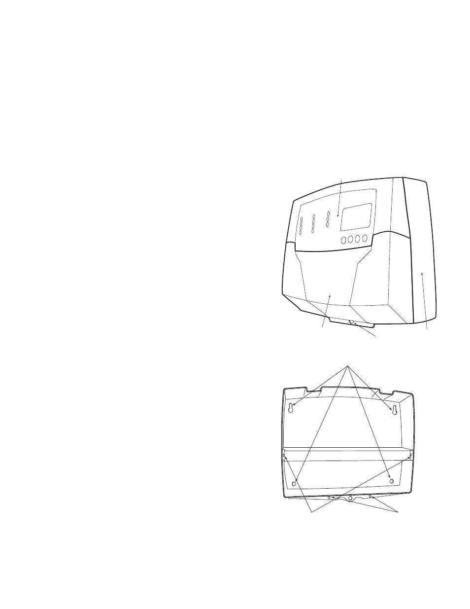
Each of the S8 or S8EXT consists of three primary enclosure components.
• The Enclosure Display Module: contains the display, buttons, LEDs
and electric wiring terminals. It has two screws to hold it to the base. A
program configuration switch, used to adjust S8 settings, is placed above
the terminals. This switch is enclosed with the enclosure wiring cover for
security. Wiring terminals are of the plug-in type to ease installation and
removal.
• The Enclosure Base: contains the holes to mount and hold the control
against the wall or any flat surface. All other enclosure components mount
on the base. The bottom section of the Enclosure Base contains the wiring
chamber with knockouts on the bottom to easy installation.
• The Enclosure Wiring Cover: seals the wires from the external
environment. It has two screws to hold it the base and a hole to secure
a lock on the wiring enclosure. A plastic web that separates the wiring
chamber into high and low volt sections has been provided.
MOUNTING THE ENCLOSURE
• Select a location near the equipment to be controlled.
• The surface should be flat, and be sufficiently wide and strong to hold the
S8 or S8EXT.
• Keep the control away from extreme heat, cold, or humidity. Ambient
operating temperature is from 20 to 120°F.
• Remove the Enclosure Wiring Cover from the control enclosure by
removing the two bottom screws.
• Remove the Enclosure Display Module by removing the middle screws.
• Screw the Enclosure Base to the surface through the upper and lower
mounting holes on the back of the enclosure.
• Replace the Enclosure Display Module and replace the middle screws.
• Do not replace the enclosure wiring cover until all wiring is done.
• When purchasing a padlock for the enclosure, the maximum shank diameter
should not exceed ¼"
Mounting Base
Display Mounting Screws
Wiring Cover Mounting Screws
Enclosure Display Module
Enclosure Wiring Cover
Enclosure Base
Hole for optional
Padlock (not supplied)