Page 11 laars sequencing controls s8 & s8ext, Wiring the dhw pump (terminals 21, 22), Wiring the stages (terminals 3 to 17) – LAARS S8Ext - Installation Manual User Manual
Page 11: Lo hi unit1 stages lo hi unit2 stages
Page 11
LAARS Sequencing Controls S8 & S8EXT
• In Cooling applications, the system relay will energize when the outdoor temperature is above the Outdoor Cutoff setting.
• A typical use of the SYS output is to activate a system pump starter. The pump can run whenever there is a call for heat/cool.
When stages are no longer required, the pump will stay active for an adjustable Run-On delay.
System Output Operation in Reset Mode
• The SYS output relay will energize whenever the outdoor temperature is below the Outdoor Cutoff.
• The SYS will remain constantly energized while the outdoor temperature is below the Outdoor Cutoff.
• When the outdoor temperature rises 2°F above the Outdoor Cutoff, the SYS output will remain energized for the period set by
the System Run-On.
• The SYS output has one Normally Open (N.O.) relay that acts as a dry contact only. It does not source any power.
• Class 1 voltages must enter the enclosure through a different opening from any Class 2 voltage wiring.
WIRING THE DHW PUMP (TERMINALS 21, 22)
The S8 can control the DHW Pump when the DHW Pump Output option is activated in the Startup Menu..
• The S8 will energize the DHW Pump whenever there is a call for DHW using a dry contact or when the DHW
temp falls below the DHW Set Point and DHW Differential.
• The DHW Pump output is Normally Open (N.O.) dry contact only. It does not source any power.
• Class 1 voltages must enter the enclosure through a different opening from any Class 2 voltage wiring.
Line
Neutral
120VAC
Power Source
Sensor Shiled
Use Copper Conductors Only.
CAUTION:
Risk of Electric Shock.
PWR
L N
1 2
SENSORS MUST BE GOLD SERIES
SYSTEM
3
DHW
PUMP
5
Stage A
7
Stage B
9
Stage C
11
13
Stage E
15
Stage F
17
Stage D
6
8
10
12
14
16
18
RS485
4
Stage G
19
Stage H
21
OUTDOOR
TEMP
27
29
31
DHW
33
SHUTDOWN
/SETBACK
35
RETURN
TEMP
20
22
28
30
32
34
36
25
26
PRESS
+ -
37
38
PROVE
SYSTEM
TEMP
PROGRAM
RUN
OUTPUT RATING: 6 AMP RESISTIVE, 1 AMP PILOT DUTY PER OUTPUT AT 120VAC.
23 24
COMB.
AIR
DO NOT APPLY ANY VOLTAGE TO INPUT TERMINALS
Outdoor Sensor
Prove Dry Contact
Sensor Shiled
System Sensor
Sensor Shiled
Return Sensor
Shutdown Dry Contact
Sensor Shiled
DHW Sensor
Lo Hi
Unit1
Stages
Unit1
Pump
Lo Hi
Unit2
Stages
Unit2
Pump
System
Pump
DHW
Pump
Comb.
Air
Damper
Use Copper Conductors Only.
CAUTION:
Risk of Electric Shock.
PWR
L N
1 2
SENSORS MUST BE GOLD SERIES
SYSTEM
3
DHW
PUMP
5
Stage A
7
Stage B
9
Stage C
11
13
Stage E
15
Stage F
17
Stage D
6
8
10
12
14
16
18
RS485
4
Stage G
19
Stage H
21
OUTDOOR
TEMP
27
29
31
DHW
33
SHUTDOWN
/SETBACK
35
RETURN
TEMP
20
22
28
30
32
34
36
25
26
PRESS
+ -
37
38
PROVE
SYSTEM
TEMP
PROGRAM
RUN
OUTPUT RATING: 6 AMP RESISTIVE, 1 AMP PILOT DUTY PER OUTPUT AT 120VAC.
23 24
COMB.
AIR
DO NOT APPLY ANY VOLTAGE TO INPUT TERMINALS
Setback Dry Contact
Lo Hi
Unit1
Stages
Lo Hi
Unit2
Stages
WIRING THE COMBUSTION AIR DAMPER (TERMINALS 23, 24)
The S8 can control the Combustion Air Damper when the Comb. Air Output option is activated in the Startup
Menu.
• The S8 will energize the Combustion Air Damper relay whenever there is a call to energize any of the unit
stages.
• The Comb. Air output has one Normally Open (N.O.) dry contact relay. It does not source any power.
• Class 1 voltages must enter the enclosure through a different opening from any Class 2 voltage wiring.
• In this scenario, the Prove input will be used to check on the Combustion Air Damper status.
Line
Neutral
120VAC
Power Source
Sensor Shiled
Use Copper Conductors Only.
CAUTION:
Risk of Electric Shock.
PWR
L N
1 2
SENSORS MUST BE GOLD SERIES
SYSTEM
3
DHW
PUMP
5
Stage A
7
Stage B
9
Stage C
11
13
Stage E
15
Stage F
17
Stage D
6
8
10
12
14
16
18
RS485
4
Stage G
19
Stage H
21
OUTDOOR
TEMP
27
29
31
DHW
33
SHUTDOWN
/SETBACK
35
RETURN
TEMP
20
22
28
30
32
34
36
25
26
PRESS
+ -
37
38
PROVE
SYSTEM
TEMP
PROGRAM
RUN
OUTPUT RATING: 6 AMP RESISTIVE, 1 AMP PILOT DUTY PER OUTPUT AT 120VAC.
23 24
COMB.
AIR
DO NOT APPLY ANY VOLTAGE TO INPUT TERMINALS
Outdoor Sensor
Prove Dry Contact
Sensor Shiled
System Sensor
Sensor Shiled
Return Sensor
Shutdown Dry Contact
Sensor Shiled
DHW Sensor
Lo Hi
Unit1
Stages
Unit1
Pump
Lo Hi
Unit2
Stages
Unit2
Pump
System
Pump
DHW
Pump
Comb.
Air
Damper
Use Copper Conductors Only.
CAUTION:
Risk of Electric Shock.
PWR
L N
1 2
SENSORS MUST BE GOLD SERIES
SYSTEM
3
DHW
PUMP
5
Stage A
7
Stage B
9
Stage C
11
13
Stage E
15
Stage F
17
Stage D
6
8
10
12
14
16
18
RS485
4
Stage G
19
Stage H
21
OUTDOOR
TEMP
27
29
31
DHW
33
SHUTDOWN
/SETBACK
35
RETURN
TEMP
20
22
28
30
32
34
36
25
26
PRESS
+ -
37
38
PROVE
SYSTEM
TEMP
PROGRAM
RUN
OUTPUT RATING: 6 AMP RESISTIVE, 1 AMP PILOT DUTY PER OUTPUT AT 120VAC.
23 24
COMB.
AIR
DO NOT APPLY ANY VOLTAGE TO INPUT TERMINALS
Use Copper Conductors Only.
CAUTION:
Risk of Electric Shock.
PWR
L N
1 2
SENSORS MUST BE GOLD SERIES
SYSTEM
3
DHW
PUMP
5
Stage A
7
Stage B
9
Stage C
11
13
Stage E
15
Stage F
17
Stage D
6
8
10
12
14
16
18
RS485
4
Stage G
19
Stage H
21
OUTDOOR
TEMP
27
29
31
DHW
33
SHUTDOWN
/SETBACK
35
RETURN
TEMP
20
22
28
30
32
34
36
25
26
PRESS
+ -
37
38
PROVE
SYSTEM
TEMP
PROGRAM
RUN
OUTPUT RATING: 6 AMP RESISTIVE, 1 AMP PILOT DUTY PER OUTPUT AT 120VAC.
23 24
COMB.
AIR
DO NOT APPLY ANY VOLTAGE TO INPUT TERMINALS
Setback Dry Contact
Lo Hi
Unit1
Stages
Lo Hi
Unit2
Stages
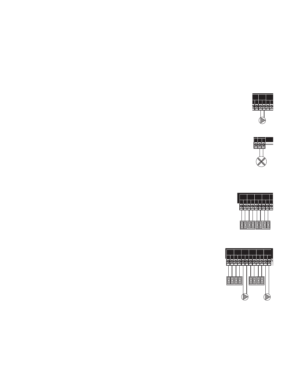
WIRING THE STAGES (TERMINALS 3 TO 17)
The S8 can be configured to operate the stages of the heating or cooling units. Moreover, it can be
configured to operate the unit pumps or valves in addition to the unit stages.
• The N.O. contacts are dry contacts only. They do not source any voltage.
• Wire the N.O. relay contacts in series with the unit’s limit circuit.
• Class 1 voltages must enter the enclosure through a different opening from any Class 2 voltage
wiring.
WIRING THE STAGE OUTPUTS
• Each Stage output (A through H) has one Normally Open (N.O.) relay contact.
• When wiring several multi-stage units, start with the lower stage of the first unit and wire it to
Output A, followed by the higher stage of the same unit and wire it to Stage B.
WIRING THE PUMP OR VALVE OUTPUTS
• If the S8 is configured to operate Stage Pumps or Valves, then, wire them using the stage after the
highest stage for that unit. That is, the low stage for the first unit must be connected to A and the
higher stage of the same unit must be connected to Stage B. The Valve or Pump for the same unit
must be connected to Stage C.
Line
Neutral
120VAC
Power Source
Sensor Shiled
Use Copper Conductors Only.
CAUTION:
Risk of Electric Shock.
PWR
L N
1 2
SENSORS MUST BE GOLD SERIES
SYSTEM
3
DHW
PUMP
5
Stage A
7
Stage B
9
Stage C
11
13
Stage E
15
Stage F
17
Stage D
6
8
10
12
14
16
18
RS485
4
Stage G
19
Stage H
21
OUTDOOR
TEMP
27
29
31
DHW
33
SHUTDOWN
/SETBACK
35
RETURN
TEMP
20
22
28
30
32
34
36
25
26
PRESS
+ -
37
38
PROVE
SYSTEM
TEMP
PROGRAM
RUN
OUTPUT RATING: 6 AMP RESISTIVE, 1 AMP PILOT DUTY PER OUTPUT AT 120VAC.
23 24
COMB.
AIR
DO NOT APPLY ANY VOLTAGE TO INPUT TERMINALS
Outdoor Sensor
Prove Dry Contact
Sensor Shiled
System Sensor
Sensor Shiled
Return Sensor
Shutdown Dry Contact
Sensor Shiled
DHW Sensor
Lo Hi
Unit1
Stages
Unit1
Pump
Lo Hi
Unit2
Stages
Unit2
Pump
System
Pump
DHW
Pump
Comb.
Air
Damper
Use Copper Conductors Only.
CAUTION:
Risk of Electric Shock.
PWR
L N
1 2
SENSORS MUST BE GOLD SERIES
SYSTEM
3
DHW
PUMP
5
Stage A
7
Stage B
9
Stage C
11
13
Stage E
15
Stage F
17
Stage D
6
8
10
12
14
16
18
RS485
4
Stage G
19
Stage H
21
OUTDOOR
TEMP
27
29
31
DHW
33
SHUTDOWN
/SETBACK
35
RETURN
TEMP
20
22
28
30
32
34
36
25
26
PRESS
+ -
37
38
PROVE
SYSTEM
TEMP
PROGRAM
RUN
OUTPUT RATING: 6 AMP RESISTIVE, 1 AMP PILOT DUTY PER OUTPUT AT 120VAC.
23 24
COMB.
AIR
DO NOT APPLY ANY VOLTAGE TO INPUT TERMINALS
Use Copper Conductors Only.
CAUTION:
Risk of Electric Shock.
PWR
L N
1 2
SENSORS MUST BE GOLD SERIES
SYSTEM
3
DHW
PUMP
5
Stage A
7
Stage B
9
Stage C
11
13
Stage E
15
Stage F
17
Stage D
6
8
10
12
14
16
18
RS485
4
Stage G
19
Stage H
21
OUTDOOR
TEMP
27
29
31
DHW
33
SHUTDOWN
/SETBACK
35
RETURN
TEMP
20
22
28
30
32
34
36
25
26
PRESS
+ -
37
38
PROVE
SYSTEM
TEMP
PROGRAM
RUN
OUTPUT RATING: 6 AMP RESISTIVE, 1 AMP PILOT DUTY PER OUTPUT AT 120VAC.
23 24
COMB.
AIR
DO NOT APPLY ANY VOLTAGE TO INPUT TERMINALS
Setback Dry Contact
Lo Hi
Unit1
Stages
Lo Hi
Unit2
Stages