S8ext a, S8ext b, S8ext – LAARS S8Ext - Installation Manual User Manual
Page 23: Xsig, 20 ma ems, System settings, Stage settings, F od, F de gh jk hi lo -- off, Op power
Page 23
LAARS Sequencing Controls S8 & S8EXT
SYSTEM SETTINGS
Button: MENU/
The System Settings menu provide access to adjusting and fine-tuning the system for enhanced
comfort and better fuel savings. The S8 behaves differently based on the selected Control
Modes (see Startup Settings).
- SYSTEM SETTINGS -
BACK SELECT
Connecting S8 to Two Extension Panels
and XSIG Interface using RS485
S8
SYSTEM
DHW PUMP
INPUT RATINGS:
115VAC 60Hz, 12VA MAX
Use Copper Conductors Only.
CAUTION:
Risk of Electric Shock.
PWR
L N
1 2
SENSORS MUST BE GOLD SERIES
SYSTEM
3
DHW
PUMP
5
Stage A
7
Stage B
9
Stage C
11
13
Stage E
15
Stage F
17
Stage D
6
8
10
12
14
16
18
RS485
SYS=
144
F OD=
35
F
GH
JK
HI LO -- OFF
4
Stage G
19
Stage H
21
OUTDOOR
TEMP
27
29
31
DHW
33
SHUTDOWN
/SETBACK
35
RETURN
TEMP
20
22
28
30
32
34
36
STAGE
MENU
Stage E
Stage F
Stage G
Stage H
Stage A
Stage B
Stage C
Stage D
25
26
PRESS
+ -
37
38
PROVE
SYSTEM
TEMP
PROGRAM
RUN
23 24
COMB.
AIR
DO NOT APPLY ANY VOLTAGE TO INPUT TERMINALS
COMB. AIR
ENCLOSED
ENERGY
MANAGEMENT
EQUIPMENT
LISTED
99RA
C
US
O
P
Power
CAUTION:
Risk of Electric Shock.
PWR
L N
1 2
I
3 4
J
5 6
K
7 8
L
9 10
M
11 12
EXTENSION
MODULE
RS-485
Ext A
INPUT RATINGS:
115VAC 60Hz, 12VA MAX
OUTPUT RATINGS:
120VAC, 6A RESISTIVE
1A PILOT DUTY, 15A TOTAL
FOR ALL CIRCUITS
Ext B
L
M
N
Comm
T
U
V
W
X
N
13 14
Q
S
U
R
T
V
S8EXT A
Use Copper Conductors Only.
I
J
K
Q
R
S
O
15 16
P
17 18
W
X
O
P
Power
CAUTION:
Risk of Electric Shock.
PWR
L N
1 2
I
3 4
J
5 6
K
7 8
L
9 10
M
11 12
EXTENSION
MODULE
RS-485
Ext A
INPUT RATINGS:
115VAC 60Hz, 12VA MAX
OUTPUT RATINGS:
120VAC, 6A RESISTIVE
1A PILOT DUTY, 15A TOTAL
FOR ALL CIRCUITS
Ext B
L
M
N
Comm
T
U
V
W
X
N
13 14
Q
S
U
R
T
V
S8EXT B
Use Copper Conductors Only.
I
J
K
Q
R
S
O
15 16
P
17 18
W
X
4-20 mA EMS
4-20mA INPUT
+
Signal GND
1
2
3
RS485
EXTENSION
CONNECTORS
XSIG 4-20mA EMS Interface
4-20mA
EMS Signal
(+)
(-)
6 Pin Phone Cable (provided with Extension)
6 Pin Phone Cable (provided with XSIG Interface)
S8
SEQUENCING CONTROL
S8EXT
SEQUENCING CONTROL
XSIG
PROGRAM CHANGE SETTINGS
To be able to change the S8 settings the Program/Run Switch must be set to Program. The
switch is located under the Enclosure Wiring Cover for security. The Enclosure Wiring
Cover can be securely closed using a padlock.
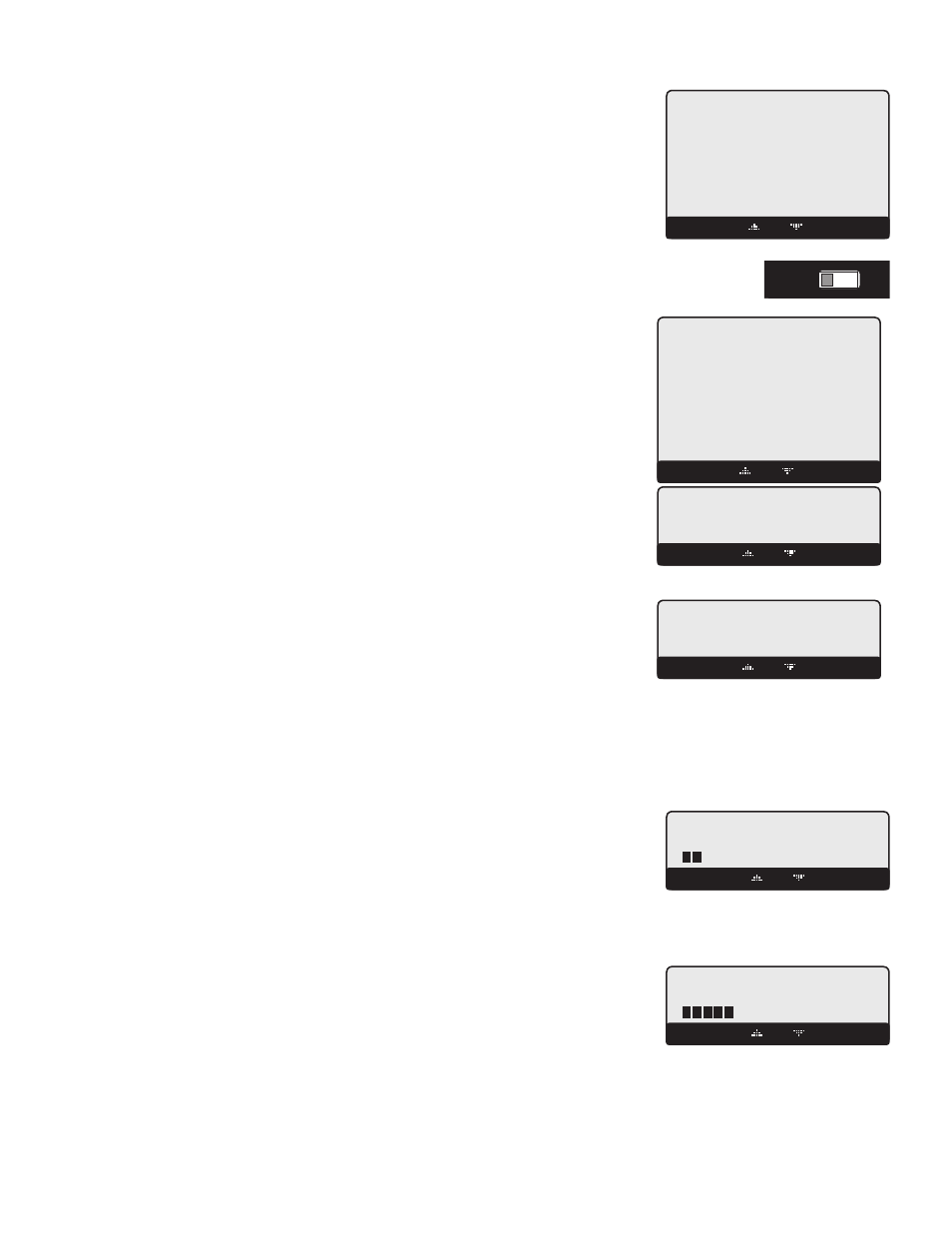
STAGE SETTINGS
Button: MENU/
-- STAGE SETTINGS --
BACK SELECT
-- REACTION TIME --
2min
BACK SAVE
REACTION TIME
Adjustable 1 - 10 minutes
Default: 2 minutes
Button: MENU/
• It is the amount of time it takes a single stage to affect the system.
• After the S8 turns on a stage trying to meet a set point, it will not turn on another stage
until the reaction time has elapsed. Then, it will recalculate if a stage is need.
• To determine the optimum time, in a heating system start with a hot system. However,
in a cooling system start with a cool system. Then, turn on a single stage and calculate
how long it takes until the system begins to respond to that stage. That period should be
set as the Reaction Time.
PURGE DELAY
Adjustable 0.0 - 10.0 minutes
Default: 0.0 minutes
Button: MENU/
in PID Logic only
• Most large units must go through a purge cycle before they are brought on line.
• When the S8 activates a unit (the lowest stage on a unit), it does not start to calculate
its output until the Purge Delay is over. This allows the unit to fully come on line and to
begin producing output.
--- PURGE DELAY ----
0.0min
[ ]
BACK SAVE
• The Purge Delay helps to prevent short cycling of a newly activated units. Once the lowest unit stage is activated, it MUST run
through the entire Purge Delay period.
• The minimum Purge Delay setting MUST be set to the time required by the units manufacturer specification.
MINIMUM RUNTIME
Adjustable 1 - 60 minutes
Default: 2 minutes
Button: MENU/
in PID Logic only
• This is the minimum amount of time any stage will run.
• For the lowest stage of a unit, the Minimum Runtime starts after the purge cycle.
- MINIMUM RUNTIME -
2min
[
]
BACK SAVE
• Initially, set the Min Runtime to half the Reaction Time.
• If System tends to overshoot, reduce the Min Runtime. If boilers tends to short cycle, increase Min Runtime.
STANDBY DELAY
Adjustable 1 - 60 minutes
Default: 10 minutes
Button: MENU/
• The Standby Delay Time only applies to units in Standby Mode.
• A Standby unit can only be activated after all the units in Auto Mode have run for the
full Standby Time.
-- STANDBY DELAY --
10min
[
]
BACK SAVE