S8ext a, S8ext b, S8ext – LAARS S8Ext - Installation Manual User Manual
Page 16: Xsig, 20 ma ems, Startup settings, Caution, F od, F de gh jk hi lo -- off, Op power
Page 16
LAARS Heating Systems
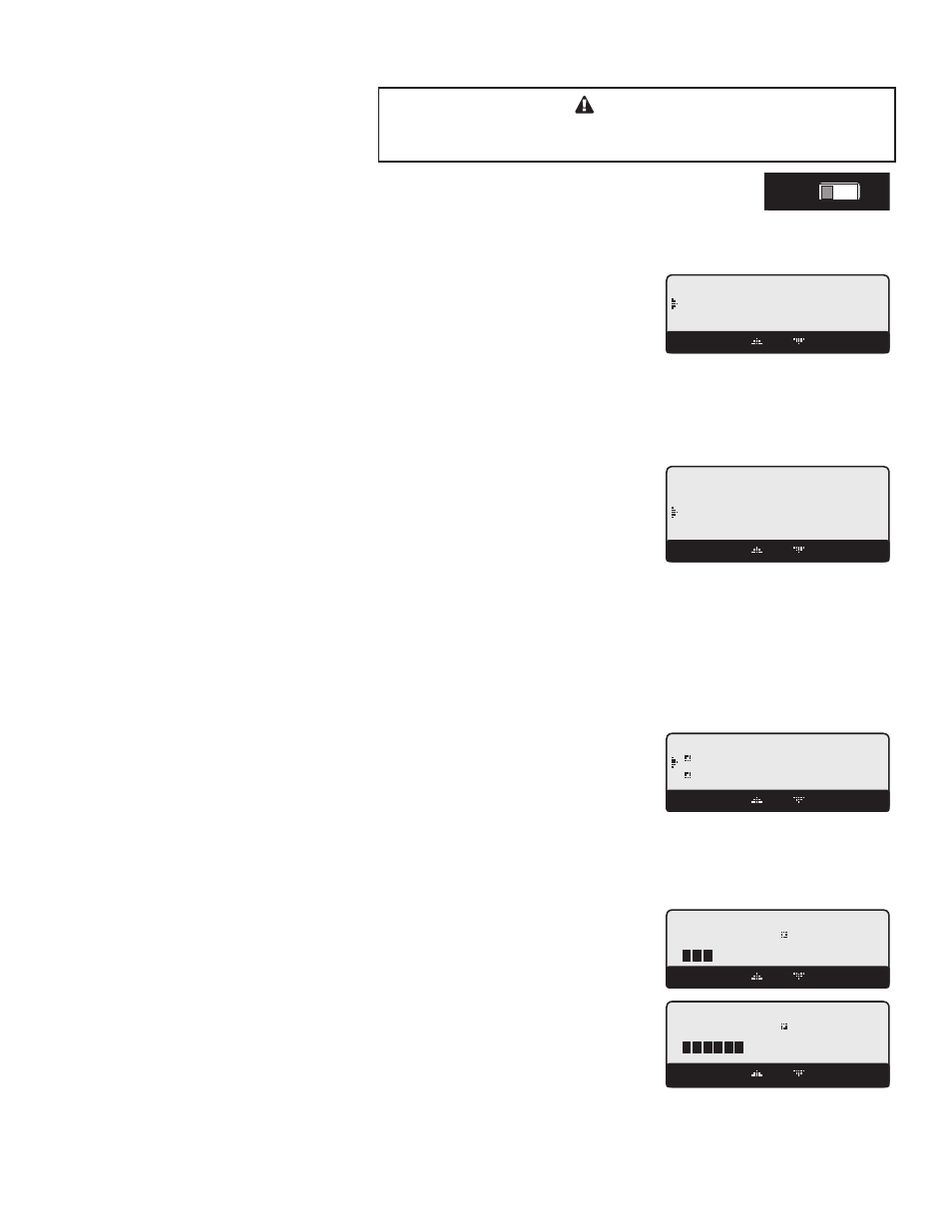
STARTUP SETTINGS
PROGRAM CHANGE SETTINGS
To be able to change the S8 settings the Program/Run Switch must be set to Program. The
switch is located under the Enclosure Wiring Cover for security. The Enclosure Wiring Cover
can be securely closed using a padlock.
Connecting S8 to Two Extension Panels
and XSIG Interface using RS485
S8
SYSTEM
DHW PUMP
INPUT RATINGS:
115VAC 60Hz, 12VA MAX
Use Copper Conductors Only.
CAUTION:
Risk of Electric Shock.
PWR
L N
1 2
SENSORS MUST BE GOLD SERIES
SYSTEM
3
DHW
PUMP
5
Stage A
7
Stage B
9
Stage C
11
13
Stage E
15
Stage F
17
Stage D
6
8
10
12
14
16
18
RS485
SYS=
144
F OD=
35
F
GH
JK
HI LO -- OFF
4
Stage G
19
Stage H
21
OUTDOOR
TEMP
27
29
31
DHW
33
SHUTDOWN
/SETBACK
35
RETURN
TEMP
20
22
28
30
32
34
36
STAGE
MENU
Stage E
Stage F
Stage G
Stage H
Stage A
Stage B
Stage C
Stage D
25
26
PRESS
+ -
37
38
PROVE
SYSTEM
TEMP
PROGRAM
RUN
23 24
COMB.
AIR
DO NOT APPLY ANY VOLTAGE TO INPUT TERMINALS
COMB. AIR
ENCLOSED
ENERGY
MANAGEMENT
EQUIPMENT
LISTED
99RA
C
US
O
P
Power
CAUTION:
Risk of Electric Shock.
PWR
L N
1 2
I
3 4
J
5 6
K
7 8
L
9 10
M
11 12
EXTENSION
MODULE
RS-485
Ext A
INPUT RATINGS:
115VAC 60Hz, 12VA MAX
OUTPUT RATINGS:
120VAC, 6A RESISTIVE
1A PILOT DUTY, 15A TOTAL
FOR ALL CIRCUITS
Ext B
L
M
N
Comm
T
U
V
W
X
N
13 14
Q
S
U
R
T
V
S8EXT A
Use Copper Conductors Only.
I
J
K
Q
R
S
O
15 16
P
17 18
W
X
O
P
Power
CAUTION:
Risk of Electric Shock.
PWR
L N
1 2
I
3 4
J
5 6
K
7 8
L
9 10
M
11 12
EXTENSION
MODULE
RS-485
Ext A
INPUT RATINGS:
115VAC 60Hz, 12VA MAX
OUTPUT RATINGS:
120VAC, 6A RESISTIVE
1A PILOT DUTY, 15A TOTAL
FOR ALL CIRCUITS
Ext B
L
M
N
Comm
T
U
V
W
X
N
13 14
Q
S
U
R
T
V
S8EXT B
Use Copper Conductors Only.
I
J
K
Q
R
S
O
15 16
P
17 18
W
X
4-20 mA EMS
4-20mA INPUT
+
Signal GND
1
2
3
RS485
EXTENSION
CONNECTORS
XSIG 4-20mA EMS Interface
4-20mA
EMS Signal
(+)
(-)
6 Pin Phone Cable (provided with Extension)
6 Pin Phone Cable (provided with XSIG Interface)
S8
SEQUENCING CONTROL
S8EXT
SEQUENCING CONTROL
XSIG
STARTUP SEQUENCE
Button: MENU/
• When powered, the S8 performs a self-test on its components. After the self-test
diagnostics have been successfully completed, the S8 will initialize the panel.
• On the first power up, the System Startup screen will appear after the initialization is
complete. If it doesn’t, the S8 has already been configured.
ARE YOU SURE?
No
Yes
BACK SAVE
• The System Startup menu sets the main parameters like the type of sensor, the type of output whether heating or cooling, the
sequencing mode, and many other parameters described in this section.
• Before entering the Startup menu, several warnings will alert you about the consequences of making Startup changes.
CONTROL MODE
Outdoor Reset, Set Point, EMS 4-20mA
Default: Set Point
Button: MENU/
• Outdoor Reset provides a variable set point based on outdoor temperature. Available for
Heating applications only.
• Outdoor Reset mode requires the use of an outdoor sensor. DO NOT select Reset without
an outdoor sensor.
---- CONTROL MODE ---
Outdoor Reset
Set Point
EMS 4-20mA
BACK SAVE
• Set Point mode does not require an outdoor sensor. If an outdoor sensor is connected in Set Point mode it will be used only as
an outdoor cutoff point. That is, to turn the stages, system, and Comb. Air relays off.
• The EMS 4-20mA allows the S8 to receive an external set point from an EMS/BMS system. This option requires the use of the
XSIG Interface (CA004200).
• You must select the 4mA (min) and 20 mA (max) Set Points in the following screens.
• Connect the XSIG Interface to the S8's RS485 connection.
DISPLAY UNIT
ºF, ºC
Default:ºF
Button: MENU/
• The S8 is designed to control boilers and chillers in hydronic environment where the
temperature is the critical factor. It allows the user of displaying temperature information
and settings in either ºF (Fahrenheit) or ºC (Celsius). Select the display unit that is best
suited for your application.
---- DISPLAY UNIT ---
F
C
BACK SAVE
SETTING THE 4MA AND 20MA SET POINTS (AVAILABLE IN 4-20MA EMS ONLY)
Default: Normal
Button: MENU/
• If EMS 4-20mA is selected from the Control Mode Menu as the temperature set point
source, the user must purchase a Laars XSIG Interface (CA004200) to accept the 4-
20mA signal and transmit it to the S8.
EMS 4mA SET POINT
100 F
[
]
BACK SAVE
• In addition, the user will need to set the temperature range parameters. First, set the 4mA
temperature, then the 20mA temperature.
• Any signal that is above or below the 4-20mA range will display the message
"Shutdown by EMS" and all stages will de-energize. However, the System,
Comb. Air, and Unit Pumps and Valves will continue for the Run-On delay period then
de-energize.
• The control will calculate the temperature for the additional 1.9mA at each end of 4
- 20mA range.
EMS 20mA SET POINT
170 F
[
]
BACK SAVE
CAUTION
A good practice after performing any Startup menu modifications is to
check all operating settings and adjustments to match the new settings.