S8ext a, S8ext b, S8ext – LAARS S8Ext - Installation Manual User Manual
Page 30: Xsig, 20 ma ems, Stage settings, Caution, F od, F de gh jk hi lo -- off, Op power
Page 30
LAARS Heating Systems
• Holding Return at 110˚F The Return sensor is reading less than the Minimum Return. S8 is trying to raise return to 110˚F.
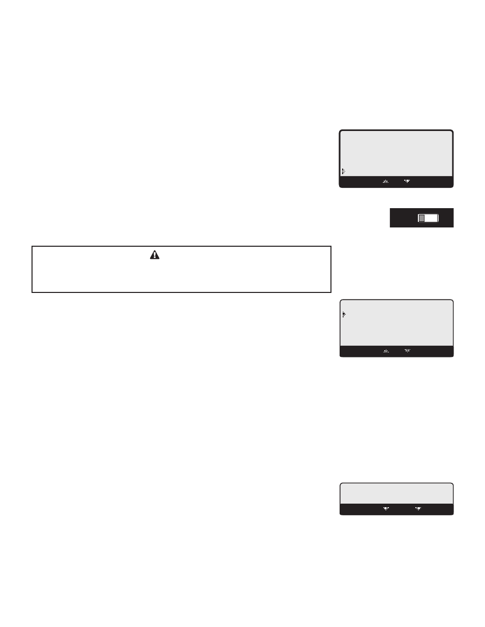
• Holding Until 150˚F
The Lead boiler is in Last Stage Hold. This example shows that the lead stage will turn off when
system temperature reaches 150˚F.
• Waiting for Comb. Prove The System or Combustion Air Damper relay is ON and the prove terminals are open before the lead
boiler relay can energize.
• SYS Prove Failure
After boilers have run for a while, Prove signal was opened. The boiler relays will de-energize.
However, the System relay will remain energized.
STAGE SETTINGS
Button: BOILER/
• In most installations, all active unit adjustments are the same, but each can be configured
differently if desired.
• When the BOILER or C.UNIT button is depressed, the Unit A Settings menu will be
shown.
• Make all the appropriate settings for Unit A (See below).
• Then select the Next Stage option from the menu to bring up the Boiler B Settings menu
and make all the settings. Continue until all boilers have been set.
• If a S8EXT is connected to the S8, scrolling through stages using the Next and Prev
Stage menu options will scroll through the S8EXT stages as well.
CAUTION
To be able to change the S8 settings, the Program/Run Switch must be set to
Program. The switch is located under the Enclosure Wiring Cover for security.
The Enclosure Wiring Cover can be securely closed using a padlock.
----- BOILER AB -----
Mode
Auto
Runtime
58Hrs
BACK SAVE
Connecting S8 to Two Extension Panels
and XSIG Interface using RS485
S8
SYSTEM
DHW PUMP
INPUT RATINGS:
115VAC 60Hz, 12VA MAX
Use Copper Conductors Only.
CAUTION:
Risk of Electric Shock.
PWR
L N
1 2
SENSORS MUST BE GOLD SERIES
SYSTEM
3
DHW
PUMP
5
Stage A
7
Stage B
9
Stage C
11
13
Stage E
15
Stage F
17
Stage D
6
8
10
12
14
16
18
RS485
SYS=
144
F OD=
35
F
GH
JK
HI LO -- OFF
4
Stage G
19
Stage H
21
OUTDOOR
TEMP
27
29
31
DHW
33
SHUTDOWN
/SETBACK
35
RETURN
TEMP
20
22
28
30
32
34
36
STAGE
MENU
Stage E
Stage F
Stage G
Stage H
Stage A
Stage B
Stage C
Stage D
25
26
PRESS
+ -
37
38
PROVE
SYSTEM
TEMP
PROGRAM
RUN
23 24
COMB.
AIR
DO NOT APPLY ANY VOLTAGE TO INPUT TERMINALS
COMB. AIR
ENCLOSED
ENERGY
MANAGEMENT
EQUIPMENT
LISTED
99RA
C
US
O
P
Power
CAUTION:
Risk of Electric Shock.
PWR
L N
1 2
I
3 4
J
5 6
K
7 8
L
9 10
M
11 12
EXTENSION
MODULE
RS-485
Ext A
INPUT RATINGS:
115VAC 60Hz, 12VA MAX
OUTPUT RATINGS:
120VAC, 6A RESISTIVE
1A PILOT DUTY, 15A TOTAL
FOR ALL CIRCUITS
Ext B
L
M
N
Comm
T
U
V
W
X
N
13 14
Q
S
U
R
T
V
S8EXT A
Use Copper Conductors Only.
I
J
K
Q
R
S
O
15 16
P
17 18
W
X
O
P
Power
CAUTION:
Risk of Electric Shock.
PWR
L N
1 2
I
3 4
J
5 6
K
7 8
L
9 10
M
11 12
EXTENSION
MODULE
RS-485
Ext A
INPUT RATINGS:
115VAC 60Hz, 12VA MAX
OUTPUT RATINGS:
120VAC, 6A RESISTIVE
1A PILOT DUTY, 15A TOTAL
FOR ALL CIRCUITS
Ext B
L
M
N
Comm
T
U
V
W
X
N
13 14
Q
S
U
R
T
V
S8EXT B
Use Copper Conductors Only.
I
J
K
Q
R
S
O
15 16
P
17 18
W
X
4-20 mA EMS
4-20mA INPUT
+
Signal GND
1
2
3
RS485
EXTENSION
CONNECTORS
XSIG 4-20mA EMS Interface
4-20mA
EMS Signal
(+)
(-)
6 Pin Phone Cable (provided with Extension)
6 Pin Phone Cable (provided with XSIG Interface)
S8
SEQUENCING CONTROL
S8EXT
SEQUENCING CONTROL
XSIG
MODE
Auto, Standby, Off, On
Default: Auto
Button: BOILER/Mode
• The S8 only controls any unit set to Auto or (after a delay) those set to Standby. None of
the other settings is recommended for output units connected to active units.
• Any output without an active unit connected must be set to Off.
• The following list describes the MODE options:
-- BOILER AB MODE -
Auto
Standby
Off
On
BACK SAVE
Auto - The S8 will control the unit’s operation to maintain the desired Set Point. Only units set to Auto can be Lead.
Standby Standby units can only be activated when all units in Auto have been at HI for an adjustable Standby delay period.
Standby is generally used when you want a specific unit to be available in extreme load conditions. Note that a Standby
unit Cannot be a Lead unit. Standby Time is only available in PID mode.
Off
Any output unit A through D not connected to a physical unit should be set to Off. The Off Mode can also be used to
disable units that are being serviced. The number of units and their stages are selected in the Startup menu.
On
The On Mode should only be used when testing a unit. The On Mode overrides the PROVE input. Once set to On the unit
will immediately start all of its stages.
RUNTIME
Clear
Button: BOILER/RunTime
• The RunTime provides an accumulative hourly run for the selected unit.
• The RunTime for a specific unit can be reset to zero by pressing the middle two buttons.
BOILER AB RUNTIME
58hrs
BACK CLEAR OK