Multiple boilers with pumps piping diagram, Page 32 laars heating systems, System – LAARS S8Ext - Installation Manual User Manual
Page 32: Dhw pump, Stage a, Stage b, Stage c, Stage e, Stage f, Stage d
Page 32
LAARS Heating Systems
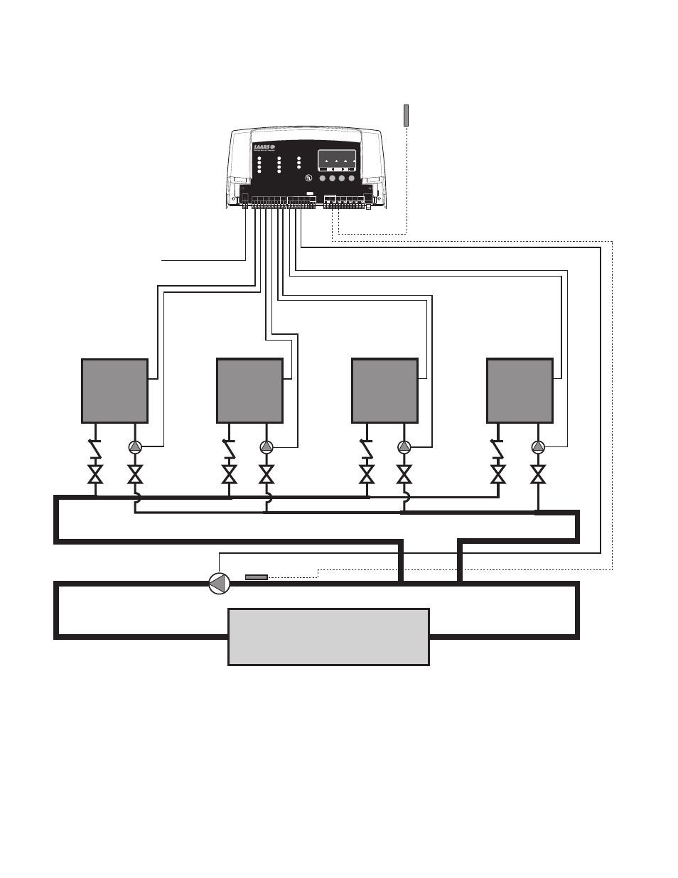
MULTIPLE BOILERS WITH PUMPS
PIPING DIAGRAM
Outdoor
Sensor
System
Sensor
120VAC
Boiler 1
Boiler 2
Boiler 3
Boiler 4
Building Heating Loop
SQ-Elite
SYSTEM
DHW PUMP
INPUT RATINGS:
115VAC 60Hz, 12VA MAX
Use Copper Conductors Only.
CAUTION:
Risk of Electric Shock.
PWR
L N
1 2
SENSORS MUST BE GOLD SERIES
SYSTEM
3
DHW
PUMP
5
Stage A
7
Stage B
9
Stage C
11
13
Stage E
15
Stage F
17
Stage D
6
8
10
12
14
16
18
RS485
SYS=
144
F OD=
35
F
GH
JK
HI LO -- OFF
4
Stage G
19
Stage H
21
OUTDOOR
TEMP
27
29
31
DHW
33
SHUTDOWN
/SETBACK
35
RETURN
TEMP
20
22
28
30
32
34
36
STAGE MENU
Stage E
Stage F
Stage G
Stage H
Stage A
Stage B
Stage C
Stage D
25
26
PRESS
+ -
37
38
PROVE
SYSTEM
TEMP
PROGRAM
RUN
23 24
COMB.
AIR
DO NOT APPLY ANY VOLTAGE TO INPUT TERMINALS
COMB. AIR
ENCLOSED
ENERGY
MANAGEMENT
EQUIPMENT
LISTED
99RA
C
US
System
Pump
S8
SEQUENCING CONTROL
System:
The S8 sequencing 4 single-stage boilers and their boiler pumps. The boilers are piped in Reverse Return on the primary
loop. The System output is controlling the System Pump.
Laars Heating Systems is aware that each installation is unique. Thus, Laars Heating Systems is not responsible for any
installation related to any electrical or plumbing diagram generated by Laars Heating Systems. The provided illustrations
are to demonstrate Laars Heating Systems’s control operating concept only.