S8ext a, S8ext b, S8ext – LAARS S8Ext - Installation Manual User Manual
Page 20: Xsig, 20 ma ems, Operating settings, Caution, F od, F de gh jk hi lo -- off, Op power
Page 20
LAARS Heating Systems
OPERATING SETTINGS
PROGRAM CHANGE SETTINGS
To be able to change the S8 settings the Program/Run Switch must be set to Program. The
switch is located under the Enclosure Wiring Cover for security. The Enclosure Wiring Cover
can be securely closed using a padlock.
Connecting S8 to Two Extension Panels
and XSIG Interface using RS485
S8
SYSTEM
DHW PUMP
INPUT RATINGS:
115VAC 60Hz, 12VA MAX
Use Copper Conductors Only.
CAUTION:
Risk of Electric Shock.
PWR
L N
1 2
SENSORS MUST BE GOLD SERIES
SYSTEM
3
DHW
PUMP
5
Stage A
7
Stage B
9
Stage C
11
13
Stage E
15
Stage F
17
Stage D
6
8
10
12
14
16
18
RS485
SYS=
144
F OD=
35
F
GH
JK
HI LO -- OFF
4
Stage G
19
Stage H
21
OUTDOOR
TEMP
27
29
31
DHW
33
SHUTDOWN
/SETBACK
35
RETURN
TEMP
20
22
28
30
32
34
36
STAGE
MENU
Stage E
Stage F
Stage G
Stage H
Stage A
Stage B
Stage C
Stage D
25
26
PRESS
+ -
37
38
PROVE
SYSTEM
TEMP
PROGRAM
RUN
23 24
COMB.
AIR
DO NOT APPLY ANY VOLTAGE TO INPUT TERMINALS
COMB. AIR
ENCLOSED
ENERGY
MANAGEMENT
EQUIPMENT
LISTED
99RA
C
US
O
P
Power
CAUTION:
Risk of Electric Shock.
PWR
L N
1 2
I
3 4
J
5 6
K
7 8
L
9 10
M
11 12
EXTENSION
MODULE
RS-485
Ext A
INPUT RATINGS:
115VAC 60Hz, 12VA MAX
OUTPUT RATINGS:
120VAC, 6A RESISTIVE
1A PILOT DUTY, 15A TOTAL
FOR ALL CIRCUITS
Ext B
L
M
N
Comm
T
U
V
W
X
N
13 14
Q
S
U
R
T
V
S8EXT A
Use Copper Conductors Only.
I
J
K
Q
R
S
O
15 16
P
17 18
W
X
O
P
Power
CAUTION:
Risk of Electric Shock.
PWR
L N
1 2
I
3 4
J
5 6
K
7 8
L
9 10
M
11 12
EXTENSION
MODULE
RS-485
Ext A
INPUT RATINGS:
115VAC 60Hz, 12VA MAX
OUTPUT RATINGS:
120VAC, 6A RESISTIVE
1A PILOT DUTY, 15A TOTAL
FOR ALL CIRCUITS
Ext B
L
M
N
Comm
T
U
V
W
X
N
13 14
Q
S
U
R
T
V
S8EXT B
Use Copper Conductors Only.
I
J
K
Q
R
S
O
15 16
P
17 18
W
X
4-20 mA EMS
4-20mA INPUT
+
Signal GND
1
2
3
RS485
EXTENSION
CONNECTORS
XSIG 4-20mA EMS Interface
4-20mA
EMS Signal
(+)
(-)
6 Pin Phone Cable (provided with Extension)
6 Pin Phone Cable (provided with XSIG Interface)
S8
SEQUENCING CONTROL
S8EXT
SEQUENCING CONTROL
XSIG
CAUTION
DO NOT turn power off to the S8
when in off-season or season is
over. If you do so, the battery
will run down and will have to
be replaced. Instead switch to
Summer or Winter.
---- SEASON ---
Winter
Summer
BACK SAVE
SEASON
Winter, Summer
Default: Winter
Button: MENU/Season
• When in Summer, and in Heating Mode, the S8 will turn all boiler relays off. However,
a DHW call will bring boilers back on if needed. The Message Display Line will display
Summer. On ther other hand, in Cooling Mode, the S8 will turn all boiler relays off
when it is in Winter setting. The Message Display Line will show Winter.
• When in Winter, the S8 will activate the Sys relay whenever the Outdoor temperature
falls to or below the Outdoor Cutoff setting in heating applications. In addition, it will
begin heating whenever the System temperature falls below the Set Point Temperature.
The Message Display Line will not display any season information. However, in
Cooling , all stages will be off and the Message Display Line will display Winter.
• When the season is over, it is a good practice to switch the S8 Season setting. This will
allow DHW calls in heating to operate the boilers when needed.
RESET RATIO
Custom, 1(8.00ºOD : 1.00ºSys) to 12 (4.00ºOD : 1.00ºSys) Default: 1(1.00ºOD : 1.00ºSys)
Button: MENU/
In Outdoor Reset Only
• The Reset Ratio applies only to Heating applications.
• The Reset Ratio determines how the System water temperature will vary with Outside
temperature. With any of the ratios, the colder it becomes outside, the hotter the
temperature of the system water. (See Understanding Operation Concept on page 5)
• With a 1.00 (OD):4.00 (SYS) ratio, the System water temperature (SYS) will increase
rapidly as the outside temperature falls, hitting the Maximum of 240°F at 35°F outside
temperature. With a 4.00 (OD):1.00 (SYS) ratio, the System water temperature (SYS)
will increase slowly as the outside temperature falls. Even at -30°F, the system water
will only be 125°F, and at 22°F outside, the system water will be 112°F. Such a low
Reset Ratio might be used with radiant floor heating applications.
• With most baseboard heating applications, a 1.00 (OD):1.00 (SYS) setting is a good
place to start. With a 1.00 (OD):1.00 (SYS) ratio, for every degree the outside
temperature falls, the system water temperature is increased one degree.
---- RESET RATIO ---
Custom
1(8.00 OD:1.00 SYS)
2(4.00 OD:1.00 SYS)
3(3.00 OD:1.00 SYS)
4(2.00 OD:1.00 SYS)
5(1.50 OD:1.00 SYS)
6(1.25 OD:1.00 SYS)
7(1.00 OD:1.00 SYS)
8(1.00 OD:1.25 SYS)
9(1.00 OD:1.50 SYS)
10(1.00 OD:2.00 SYS)
11(1.00 OD:3.00 SYS)
12(1.00 OD:4.00 SYS)
BACK SAVE
• If required: Adjust the RESET RATIO in cold weather. If the ambient building
temperatures are too cold in cold weather, move the ratio to a higher selection. That is,
if 1.00 (OD):1.00 (SYS) was initially selected, change the selection to 1.00 (OD):1.25
(SYS). If the building temperatures are too warm in cold weather, move the ratio to
a lower selection. That is, if 1.00 (OD):1.00 (SYS) was initially selected, change the
selection to 1.25 (OD):1.00 (SYS).
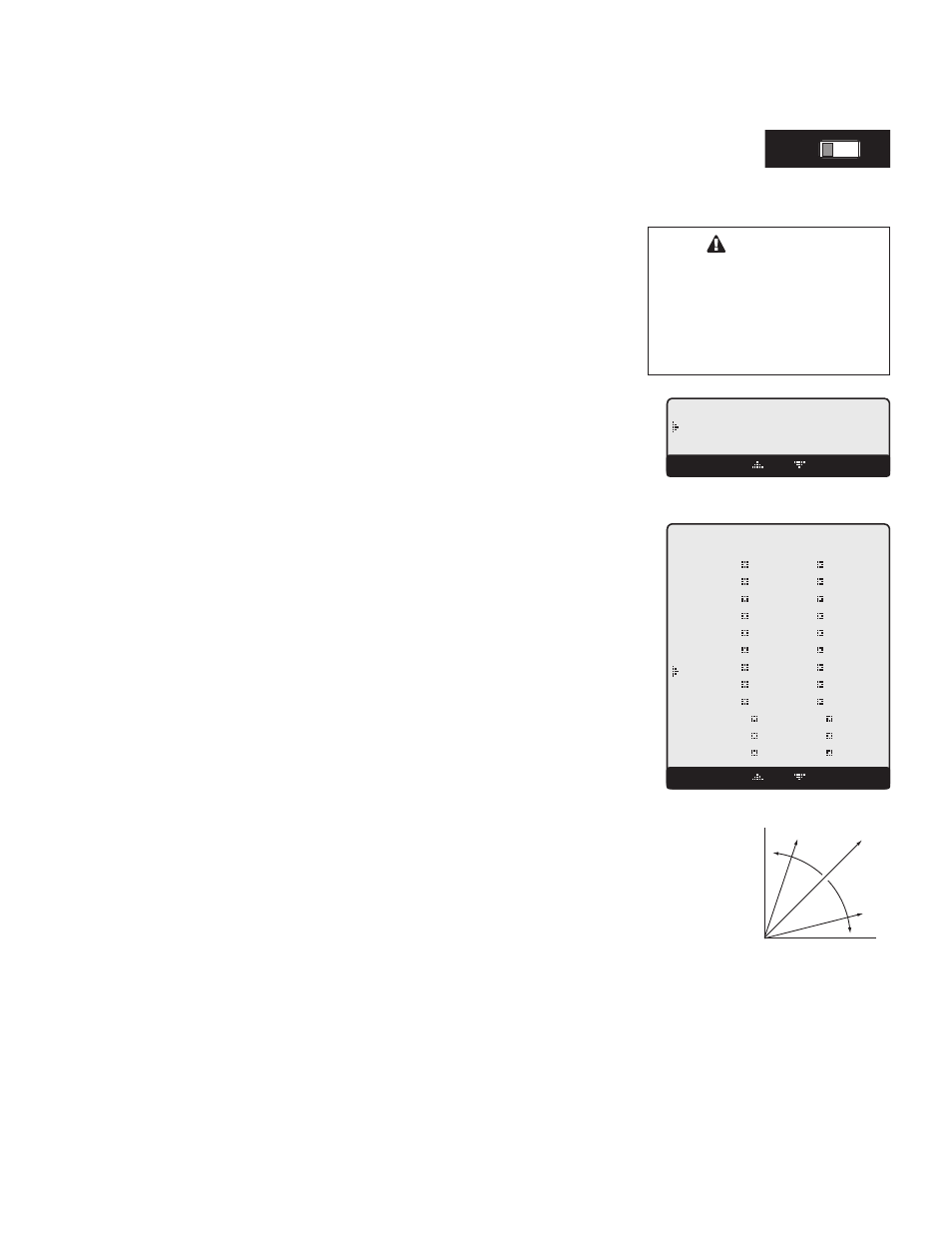
Outdoor Temperature
W
at
er
T
em
pe
ra
tu
re
70
40
50
60
130
120
110
100
Outdoor Temperature
W
at
er
T
em
pe
ra
tu
re
70
40
50
60
110
100
90
80
Outdoor Temperature
W
at
er
Te
m
pe
ra
tu
re
70
40
50
60
150
140
130
120
1:4
With a 0° Offset, the
ratio curves begin at
100° Water Temperature.
With a -20° Offset, the
ratio curves begin at
80° Water Temperature.
With a +20° Offset, the
ratio curves begin at
120° Water Temperature.
1:4
1:4
1:1
1:1
1:1
4:1
4:1
4:1
90
100
+20 Offset
-20 Offset
Outdoor Temperature
W
at
er
T
em
pe
ra
tu
re
70
40
50
60
130
120
110
100
1:4
1:1
4:1
Colder
Warmer
CUSTOMIZED RESET RATIO
Button: MENU/
• F
can be used.
• The Custom Reset Ratio is only available when Custom is selected from the Reset Ratio menu option. It provides the user
with the capability of assigning two points on the reset ratio diagram and use the line that connects those two points as the
customized reset ratio curve. Each of the two points will need a specific System and Outdoor Temperature to identify it on the
diagram.