Carrier 50ZH024-060 User Manual
Page 8
HIGH-VOLTAGE CONNECTIONS — The unit must have
a separate electrical service with a field-supplied, water-
proof disconnect switch mounted at, or within sight from the
unit. Refer to the unit rating plate for maximum fuse/circuit
breaker size and minimum circuit amps (ampacity) for wire
sizing. See Table 3 for electrical data.
The field-supplied disconnect may be mounted on the unit
over the high-voltage inlet hole. See Fig. 2-4.
Operation of unit on improper line voltage constitutes
abuse and may cause unit damage that could affect
warranty.
ROUTING POWER LEADS INTO UNIT — Use only cop-
per wire between disconnect and unit. The high-voltage leads
should be in a conduit until they enter the unit; conduit ter-
mination at the unit must be watertight. Run the high-
voltage leads through the hole on the control box side of the
unit (see Fig. 10 for location). When the leads are inside the
unit, run leads to the control box (Fig. 11). For single-phase
units, connect leads to the black and yellow wires; for 3-phase
units, connect the leads to the black, yellow, and blue wires
(see Fig. 12).
CONNECTING GROUND LEAD TO UNIT GROUND
— Refer to Fig. 11 and 12. Connect the ground lead to the
chassis using the unit ground lug in the control box.
ROUTING CONTROL POWER WIRES — Form a drip-
loop with the thermostat leads before routing them into the
unit. Route the thermostat leads through grommeted hole pro-
vided in unit (see Fig. 10) into unit control box. Connect
thermostat leads to unit control power leads as shown in
Fig. 13.
Route thermostat wires through grommet providing a drip
loop at the panel. Connect low-voltage leads to the thermo-
stat as shown in Fig. 13.
The unit transformer supplies 24-v power for complete
system including accessory electrical heater. Transformer is
factory wired for 230-v operation. If supply voltage is
208 v, rewire transformer primary as described in the
Special Procedures for 208-v Operation section below.
ACCESSORY ELECTRIC HEAT WIRING — Refer to ac-
cessory electric heat installation instructions for information
on installing accessory electric heat. Accessory electric heat
wiring is shown in Fig. 14.
SPECIAL PROCEDURES FOR 208-V OPERATION
Make sure that the power supply to the unit is switched
OFF before making any wiring changes. Electrical shock
can cause personal injury or death.
1. Disconnect the orange transformer-primary lead from the
contactor. See unit wiring label.
2. Remove the wirenut from the terminal on the end of the
red transformer-primary lead.
3. Save the wirenut.
4. Connect the red lead to the contactor terminal from which
the orange lead was disconnected.
5. Using the wirenut removed from the red lead, insulate
the loose terminal on the orange lead.
6. Wrap the wirenut with electrical tape so that the metal
terminal cannot be seen.
Indoor blower-motor speeds may need to be changed for
208-v operation. Refer to Indoor Airflow and Airflow
Adjustments section on page 14.
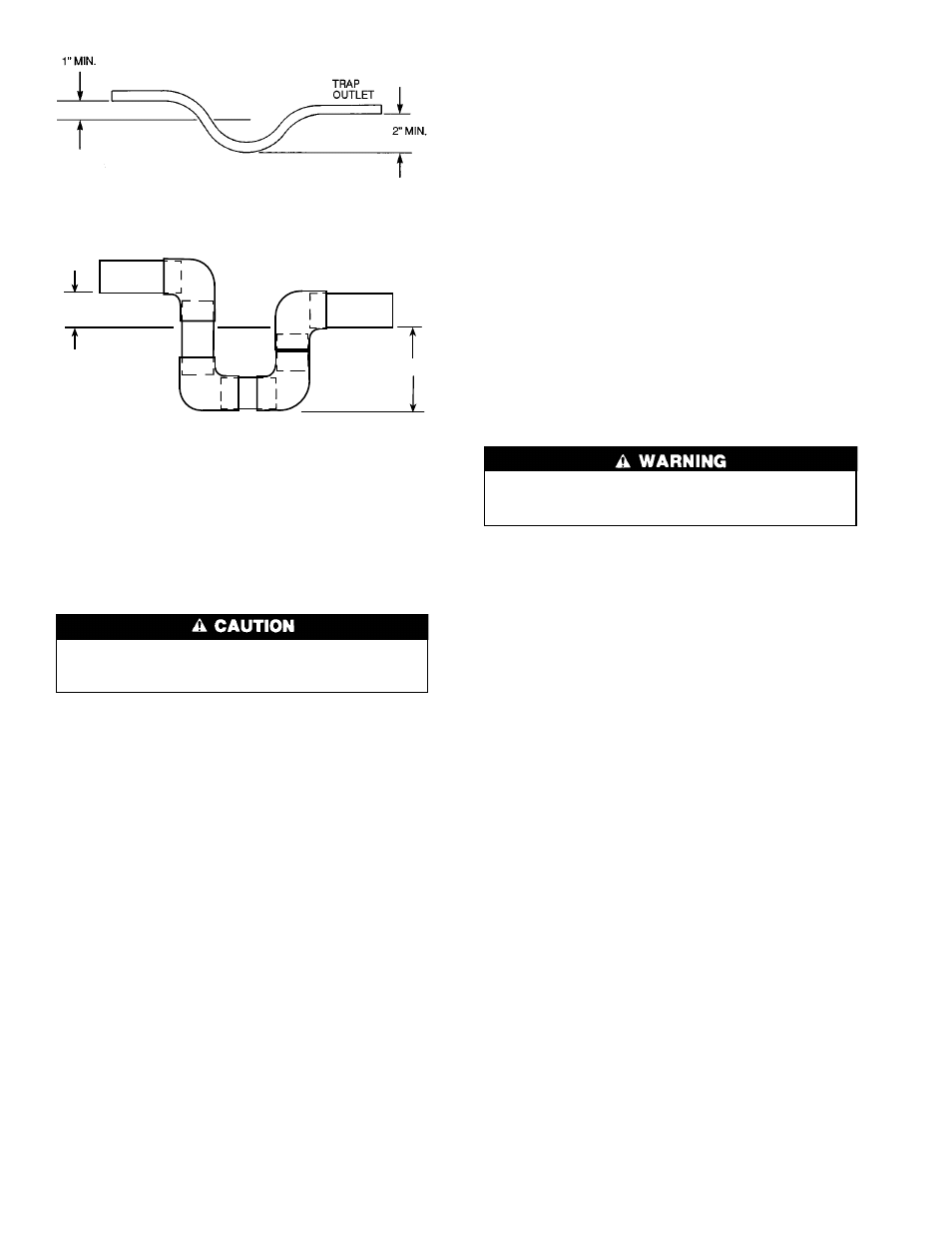
Fig. 9A — Condensate Trap (Using Tubing)
TRAP
OUTLET
1" MIN.
2" MIN.
Fig. 9B — Condensate Trap (Using PVC Piping)
8