Carrier 50ZH024-060 User Manual
Page 6
Select and size ductwork, supply-air registers and
return-air grilles according to ASHRAE (American Society
of Heating, Refrigeration, and Air Conditioning Engineers)
recommendations.
Use the duct flanges provided on the supply- and return-
air openings on the side of the unit. See Fig. 2-4 for con-
nection sizes and locations. The 14-in. round duct collars are
shipped inside the 024-048 size units, attached to the indoor
blower. They are field-installed and must be removed from
the indoor cavity prior to start-up, even if they are not used
for installation.
INSTALL FLANGES FOR DUCTWORK CONNECTIONS
(50ZH060 Only) — The 50ZH060 units are shipped with
flanges which must be field-installed on the unit.
To install unit flanges:
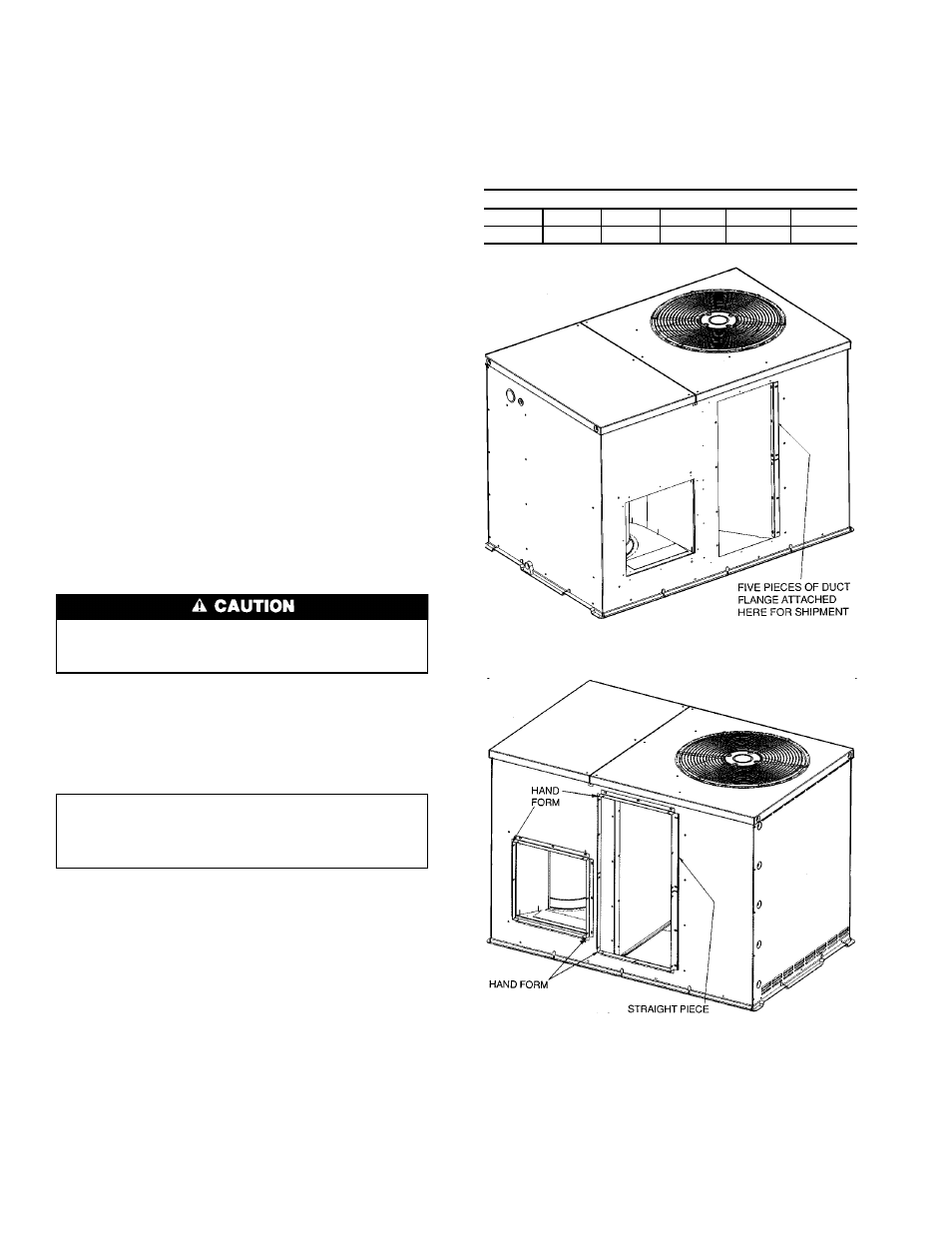
1. Five pieces of flange are shipped on the return-air open-
ing of the unit. Remove the flanges from the shipping po-
sition. See Fig. 5. Screws are field-supplied.
2. One piece of flange is used as it is shipped (straight). Bend
the other 4 pieces at right angles.
3. Install the straight flange on the right side of the return
air opening in holes provided. See Fig. 6. Flanges should
stick out from unit to allow for connection of ductwork.
4. Install 2 hand-formed flanges onto return air opening in
holes provided to form a rectangle around the return air
opening.
5. Install remaining 2 hand-formed flanges around dis-
charge air opening in holes provided.
6. Ductwork can now be attached to flanges.
INSTALLING DUCTWORK — When designing and in-
stalling ductwork, consider the following:
When connecting ductwork to units, do not drill deeper
than
3
⁄
4
inch in shaded area shown in Fig. 7 or coil may
be damaged.
• All units should have field-supplied filters installed in the
return-air side of the unit. Recommended sizes for filters
are shown in Table 1.
• Avoid abrupt duct size increases and reductions. Abrupt
change in duct size adversely affects air performance.
IMPORTANT: Use flexible connectors between
ductwork and unit to prevent transmission of vibra-
tion. Use suitable gaskets to ensure weathertight and
airtight seal.
• Size ductwork for cooling air quantity (cfm). The mini-
mum air quantity for proper electric heater operation is
listed in Table 2. Heater limit switches may trip at air quan-
tities below those recommended.
• Insulate and weatherproof all external ductwork. Insulate
and cover with a vapor barrier all ductwork passing through
conditioned spaces. Follow latest Sheet Metal and Air
Conditioning Contractors National Association (SMACNA)
and Air Conditioning Contractors Association (ACCA) mini-
mum installation standards for residential heating and air
conditioning systems.
• Secure all ducts to building structure. Flash, weather-
proof, and vibration-isolate duct openings in wall or roof
according to good construction practices.
Figure 8 shows a typical duct system with 50ZH unit
installed.
Table 2 — Minimum Airflow for Safe Electric
Heater Operation (Cfm)
SIZE
024
030
036
042
048
060
600
750
900
1050
1200
1500
Fig. 5 — Shipping Location of Duct Flanges
(Size 060 Only)
Fig. 6 — Flanges Installed on 50ZH060 Units
6