Carrier 50ZH024-060 User Manual
Page 14
INDOOR AIRFLOW AND AIRFLOW ADJUSTMENTS
For cooling operation, the recommended airflow is
350 to 450 cfm per each 12,000 Btuh of rated cooling
capacity.
Table 4 shows dry coil air delivery for horizontal dis-
charge units.
NOTE: Be sure that all supply- and return-air grilles are open,
free from obstructions, and adjusted properly.
Disconnect electrical power to the unit before changing
blower speed. Electrical shock can cause personal in-
jury or death.
Airflow can be changed by changing the lead connections
of the blower motor.
Units 50ZH024,036, 048, and 060 blower motors are fac-
tory wired for low speed operation. Units 50ZH030 and 042
are factory wired for medium speed operation.
For 208/230-v Blower Motors:
The motor leads are color-coded as follows:
3-SPEED
2-SPEED
black = high speed
black = high speed
blue
= medium speed
red
= low speed
red
= low speed
To change the speed of the blower motor, remove the fan
motor speed leg lead from the indoor fan relay (IFR) and
replace with lead for desired blower motor speed. Insulate
the removed lead to avoid contact with chassis parts.
Table 4 — Dry Coil Air Delivery — Horizontal
Discharge
UNIT
50ZH
IFM SPEED
SETTING
AIRFLOW
(CFM)
ESP
(in. wg)
POWER
(watts)
024
LOW
800
0.30
282
MED
800
0.65
349
HIGH
800
0.80
439
030
LOW*
1000
—
—
MED
1000
0.35
370
HIGH
1000
0.65
460
036
LOW
1200
0.30
445
MED
1200
0.50
480
HIGH
1200
0.65
530
042
LOW*
1400
—
—
MED
1400
0.30
495
HIGH
1400
0.60
571
048†
LOW
1600
0.50
650
—
—
—
—
HIGH
1600
0.65
720
060
LOW
2000
0.15
850
MED
2000
0.60
900
HIGH
2000
0.65
945
LEGEND
IFM — Indoor Fan Motor
*Unit is factory set on medium speed. This airflow is not obtainable
at low speed.
†048 model has low and high speed only.
NOTE: Values are at 230 v; Deduct 10% for 208 v.
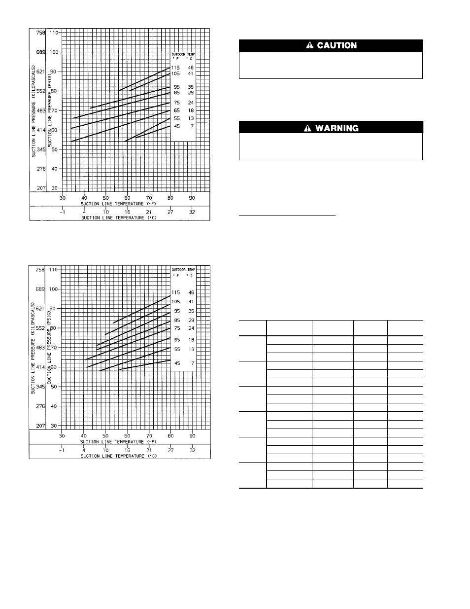
Fig. 19 — Cooling Charging Chart — 50ZH048
Fig. 20 — Cooling Charging Chart — 50ZH060
14