Step 6 — provide for condensate disposal, Step 7 — install electrical connections – Carrier 50ZH024-060 User Manual
Page 7
CONVERTING HORIZONTAL DISCHARGE UNITS TO
DOWNFLOW (VERTICAL) DISCHARGE
Before performing service or maintenance operations on
the system, turn off the main power to the unit. Turn off
accessory heater power switch if applicable. Electrical
shock can cause personal injury.
Units are dedicated side-supply products. They are not con-
vertible to vertical air supply. A field-supplied plenum must
be used to convert to vertical air discharge.
Step 6 — Provide for Condensate Disposal
NOTE: Be sure that condensate-water disposal methods com-
ply with local codes, restrictions, and practices.
Unit removes condensate through a 1
3
⁄
64
-in. ID hole
(using
3
⁄
4
-in. OD piping or tubing) which is located at the
end of the unit. See Fig. 2-4 for location of condensate
connection.
Condensate water can be drained directly onto the roof in
rooftop installations (where permitted) or onto a gravel apron
in ground-level installations. Install a field-supplied conden-
sate trap at end of condensate connection to ensure proper
drainage. Make sure that the outlet of the trap is at least
1 in. lower than the drain pan condensate connection to
prevent the pan from overflowing. See Fig. 9A and 9B. Prime
the trap with water. When using a gravel apron, make sure
it slopes away from the unit.
If the installation requires draining the condensate water
away from the unit, install a 2-in. trap using
3
⁄
4
-in. tubing or
piping. See Fig. 9A and 9B. Make sure that the outlet of the
trap is at least 1 in. lower than the unit drain pan condensate
connection to prevent the pan from overflowing. Prime the
trap with water. Connect a drain tube using a minimum of
3
⁄
4
-in. PVC,
3
⁄
4
-in. CPVC, or
3
⁄
4
-in. copper pipe (all field sup-
plied). Do not undersize the tube. Pitch the drain tube down-
ward at a slope of at least 1 in. for every 10 ft of horizontal
run. Be sure to check the drain tube for leaks. Prime trap at
the beginning of the cooling season start-up. Allowable glues
for condensate trap connection are: Standard ABS, CPVC,
or PVC cement.
Step 7 — Install Electrical Connections
The unit cabinet must have an uninterrupted, unbroken
electrical ground to minimize the possibility of personal
injury if an electrical fault should occur. This ground
may consist of an electrical wire connected to the unit
ground in the control compartment, or conduit ap-
proved for electrical ground when installed in accor-
dance with NEC (National Electrical Code), ANSI
(American National Standards Institute)/NFPA (latest edi-
tion) (in Canada, Canadian Electrical Code CSA
[Canadian Standard Association] C22.1) and local elec-
trical codes. Failure to adhere to this warning could re-
sult in personal injury or death.
Failure to follow these precautions could result in dam-
age to the unit being installed:
1. Make all electrical connections in accordance with
NEC ANSI/NFPA (latest edition) and local elec-
trical codes governing such wiring. In Canada, all
electrical connections must be in accordance with CSA
Standard C22.1 Canadian Electrical Code Part 1
and applicable local codes. Refer to unit wiring
diagram.
2. Use only copper conductor for connections between
field-supplied electrical disconnect switch and unit.
DO NOT USE ALUMINUM WIRE.
3. Be sure that high-voltage power to unit is within op-
erating voltage range indicated on unit rating plate.
On 3-phase units, ensure that phases are balanced within
2%. Consult local power company for correction of
improper voltage and/or phase imbalance.
4. Insulate low-voltage wires for highest voltage con-
tained within conduit when low-voltage control wires
are run in same conduit as high-voltage wires.
5. Do not damage internal components when drilling
through any panel to mount electrical hardware, con-
duit, etc.
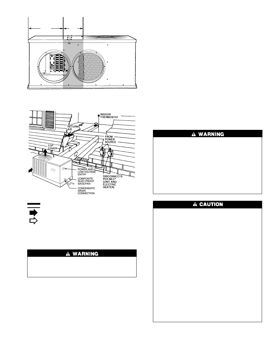
19.17
″
3.92
″
Fig. 7 — Area Not to Be Drilled More Than
3
⁄
4
-in.
Power Wiring
Control Wiring
Outdoor Airflow
Indoor Airflow
*Separate disconnect per NEC
(National Electrical Code) required
for electric heater when single-
point connection is not used.
Fig. 8 — Typical Installation
7