Fiber opitc cable connection parameters, Fiber optical patch cables, Power information – Interlogix MCR205-1T/1S User Manual User Manual
Page 61: Meters 55
IFS MCR205-1T/1S User Manual
55
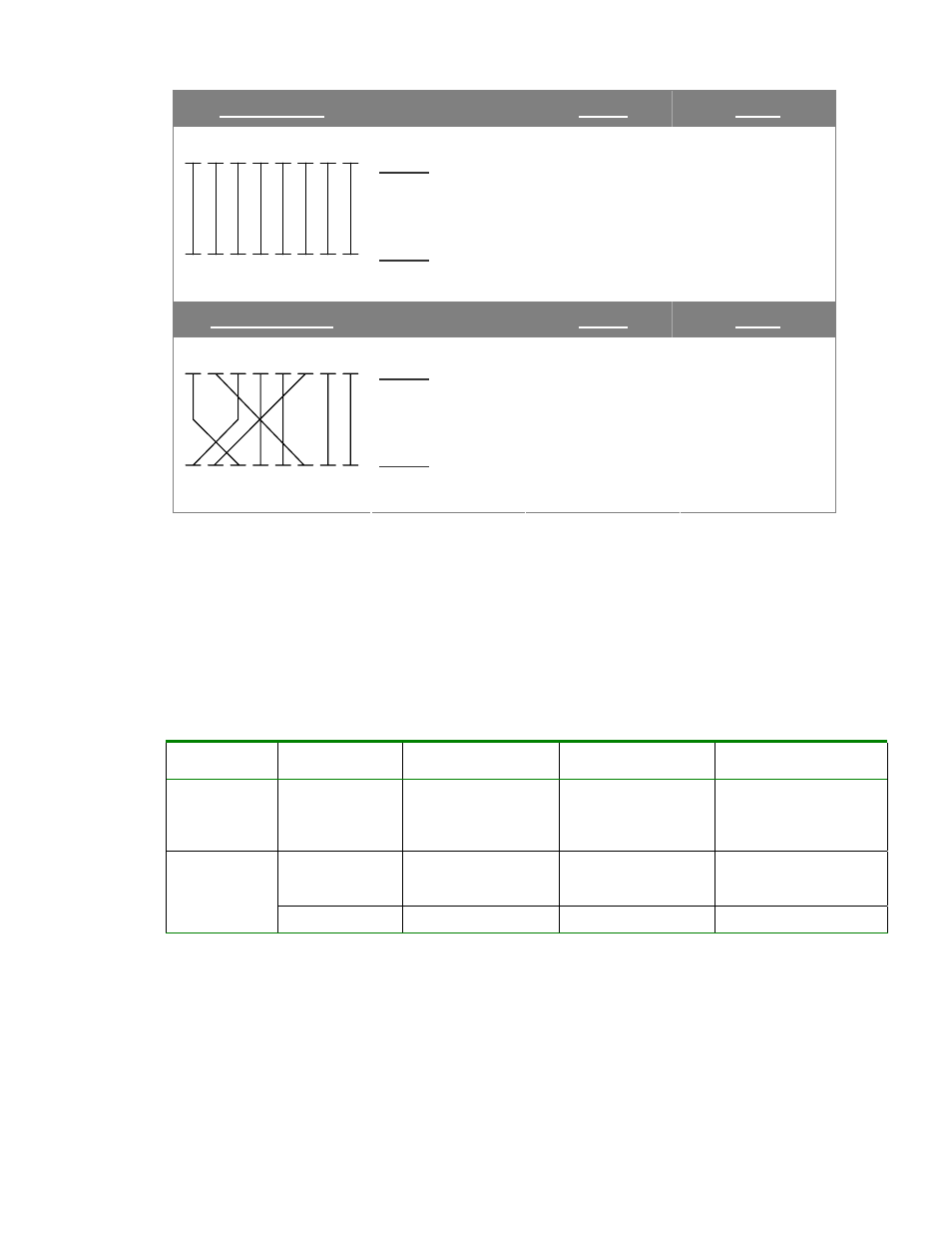
Straight Cable
SIDE 1
SIDE2
SIDE 1
1
2
3
4
5
6
7
8
1
2
3
4
5
6
7
8
SIDE 2
1 = White / Orange
2 = Orange
3 = White / Green
4 = Blue
5 = White / Blue
6 = Green
7 = White / Brown
8 = Brown
1 = White / Orange
2 = Orange
3 = White / Green
4 = Blue
5 = White / Blue
6 = Green
7 = White / Brown
8 = Brown
Crossover Cable
SIDE 1
SIDE2
SIDE 1
1
2
3
4
5
6
7
8
1
2
3
4
5
6
7
8
SIDE 2
1 = White / Orange
2 = Orange
3 = White / Green
4 = Blue
5 = White / Blue
6 = Green
7 = White / Brown
8 = Brown
1 = White / Green
2 = Green
3 = White / Orange
4 = Blue
5 = White / Blue
6 = Orange
7 = White / Brown
8 = Brown
Please make sure your connected cables are with same pin assignment and
color as above picture before deploying the cables into your network.
Fiber Opitc Cable Connection Parameters
The optical details are as follows:
Fiber Optical Patch Cables
Standard
Fiber
Diameter (micron)
Modal Bandwidth
(MHz * km)
Max. Distance
(meters)
1000Base-SX Multi-mode
62.5
62.5
50
50
100
200
400
500
220
275
500
550
Multi-mode 62.5
50
50
5
4
5
550
1000Base-LX
Single-mode 9
N/A
5000*
Power Information
The power jack of the MCR205-1T/1S is with 2.5mm in the central post and
required +5VDC power input. It is compatible with the MCR-R15. Should you
have a problem with the the power connection, please contact your local sales
representative.