Intek RheoVac CMS User Manual
Page 18
September 2013
14
© Intek, Inc. 2013
Revision D
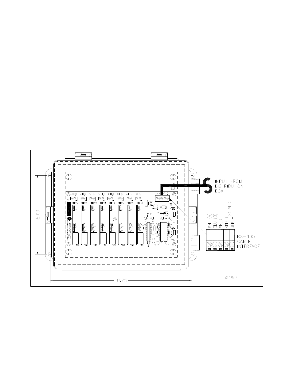
2.2.4 4-20mA Transmitter Box (optional) – For driving eight (8) remote 4-20 mA analog
signals
The 4-20mA transmitter component is optional, see Figure 7. Note: Intek recommends using the
network connection for all data transmissions and communications with the RheoVac MSP.
1. Connect the DeviceNet 5711 cable. The color code for this cable is: RS-485
communications: white (A), blue (B) and shield (SH); power: 24Vdc, red (+), and black
(
).
2. Connect up to eight (8) signal wire pairs to the indicated terminals for isolated 4-20mA
outputs.
3. CMS 4-20mA transmitters are configured as active (transmitter sources the current) when
shipped. To change to the passive mode (receiver to source the current), extract each
small 4-20 board, find the JP1 pins, and move the two jumpers from the “Act” pins to the
“Pass” pins (two positions to the right of factory settings). Figure 8 shows the current
output circuit. Figure 8 also illustrates the active mode and the passive mode
configurations.
4. Refer to Section 4.1 for general information on standard transmitter channel-to-
instrument output mapping. Refer to SECTION 8 - CUSTOM INFORMATION for
transmitter channel-to-instrument 4-20mA outputs mapping.
Figure 7: Optional 4-20mA Transmitter Box