Figure 5: serial communication interface – Intek RheoVac CMS User Manual
Page 16
September 2013
12
© Intek, Inc. 2013
Revision D
2.2.1 Main Electronics – contains the SCADA and HMI components
1. Transmitter(s) Power/COM: A DeviceNet 5711 cable is used all probe/sensor/4-20mA
transmitters. The color code for this cable is: RS-485 communications: white (A), blue
(B) and shield (SH); power: 24Vdc, red (+), and black (
).
2. Main Power: Power connection wires should be at least 18 AWG. Connect main power
terminals to a dedicated 120 or 240 VAC, single phase, 15-amp circuit. A main power
switch is provided near the input power terminals.
3. Network Communication (Recommended): An Ethernet connection (RJ-45 style jack) is
provided. Intek recommends using this connection for all data transmissions because:
a. More measured data is accessible through the network connection.
b. Software and calibration file updates can be done remotely.
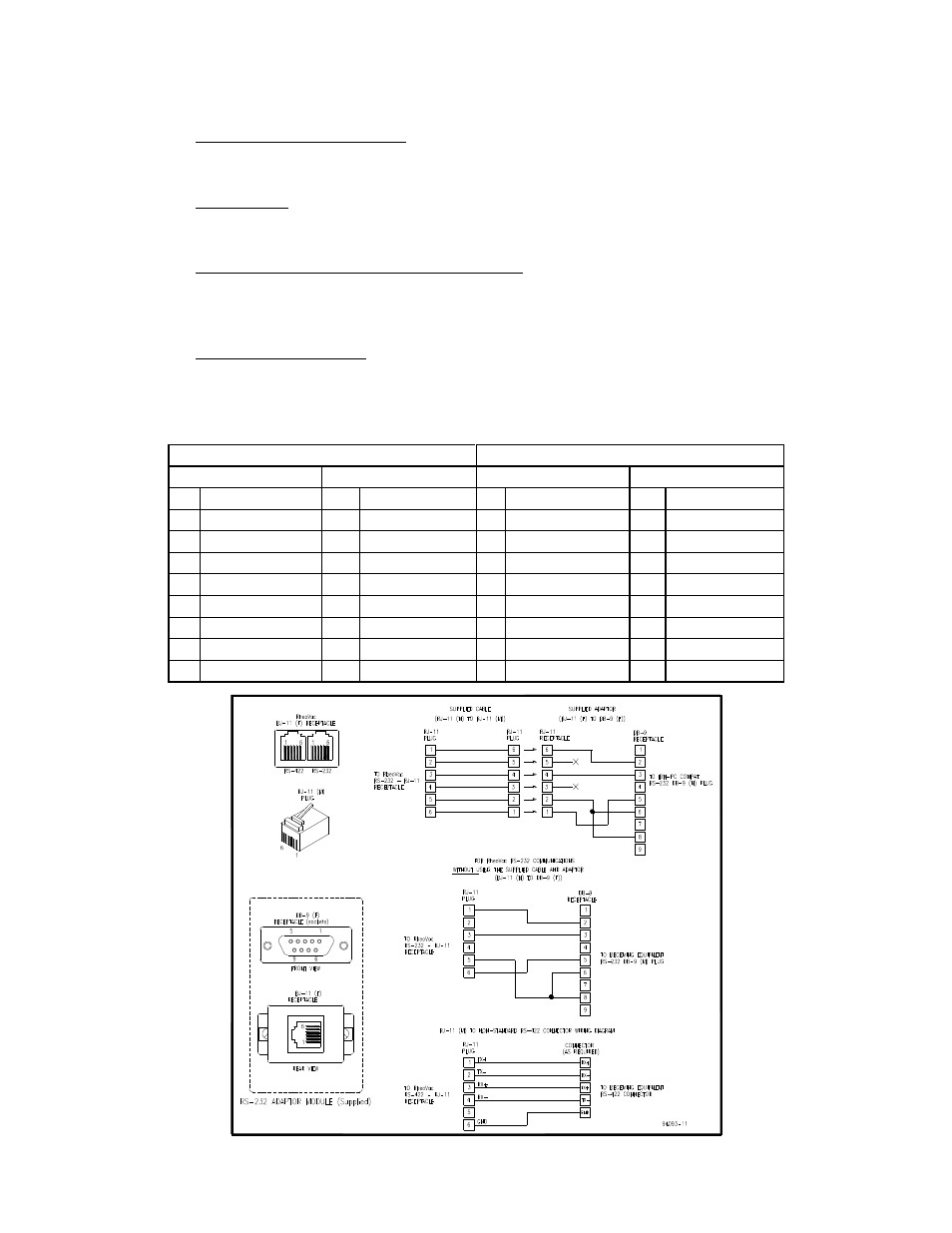
4. Serial Communication: Connector JP3 on the CPU interface PWA (printed wiring board
#08017-1) is the RS-232 and RS-422 serial communication interface. The configuration
information for a RJ-11 to DB-9 adapter is shown in Table 1 and Figure 5.
Table 1: RJ-11 to DB-9 Module Adapter
RS-232 CONFIGURATION
RS-422 CONFIGURATION
RJ-11 Pin Out
DB-9 Pin Out
RJ-11 Pin Out
DB-9 Pin Out
1
Tx (transmit)
1
N/C
1
Tx+ (transmit+)
1
Rx- (receive-)
2
N/C
2
Tx (transmit)
2
Tx- (transmit
S)
2
Rx+ (receive+)
3
Rx (receive)
3
Rx (receive)
3
Rx+ (receive-)
3
Tx+ (transmit+)
4
N/C
4
N/C
4
Rx- (receive-)
4
N/C
5
Power (+5V)
5
Ground
5
Power (+5V)
5
Ground
6
Ground
6
Pulled high
6
Ground
6
Tx- (transmit-)
7
N/C
7
7
TBD
8
Pulled high
8
8
TBD
9
N/C
9
9
TBD
Figure 5: Serial communication interface