11 flip – IC Realtime Max Series: 4/8/16 Channel D1 1.5U Standalone DVR User Manual
Page 63
53
4.9.4 Activate Patrol (tour)
In
X341H341H341H
Figure 4-46, input patrol (tour) number in the No. blank and click patrol button
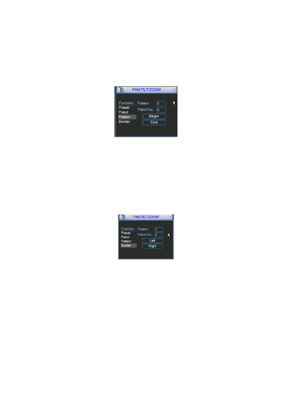
4.9.5 Pattern Setup
In Figure 4-46, click pattern button and then click “begin” button. The interface is shown as in
Figure 4-50. Then you can go to Figure 4-43 X to modify zoom, focus, and iris.
Go back to Figure 4-50 and click “end” button. You can memorize all these operations as pattern
1.
Figure 4-50
4.9.6 Activate Pattern Function
In
X346H346H346H
Figure 4-39, input mode value in the No. blank, and click pattern button.
4.9.7 Auto Scan Setup
In
X347H347H347H
Figure 4-38, click border button. The interface is shown as in
X348H348H348H
Figure 4-43.
Please go to
X349H349H349H
X349H349H349H
Figure 4-35, use direction arrows to select camera left limit
Then please go to
X350H350H350H
Figure 4-43
X
and click left limit button
Repeat the above procedures to set right limit.
Figure 4-51
4.9.8 Activate Auto Scan
In Figure 4-47, click “Auto Scan” button, the system begins auto scan. Correspondingly, the auto
scan button becomes Stop button. Click stop button to terminate scan operation.
4.11 Flip
In Figure 4-47, click page switch button, you can see an interface is shown as below. See Figure
4-52. Here you can set auxiliary function. The aux value has relation ship with the Aux button of
the decoder.
Click page switch button again, system goes back to Figure 4-43.