Die-cut drawings – Great Planes Patriot XL Kit - GPMA0450 User Manual
Page 6
Fuse = Fuselage
Stab = Horizontal Stabilizer
Fin = Vertical Fin
LE = Leading Edge
TE = Trailing Edge
LG = Landing Gear
Ply = Plywood
" = Inches
mm = Millimeters
SHCS = Socket Head Cap Screw
❏
1. Unroll the plan sheets. Re-roll the plan inside out to
make them lie flat.
❏
2. Remove all parts from the box. As you do, figure out the
name of each part by comparing it with the plan and the
parts list included with this kit. Using a felt-tip or ballpoint
pen, lightly write the part name or size on each piece to
avoid confusion later. Use the die-cut patterns to identify the
die-cut parts and mark them before removing them from the
sheet. Save all leftovers. If any of the die-cut parts are
difficult to punch out, do not force them! Instead, cut around
the parts with a hobby knife. After punching out the die-cut
parts, use your bar sander to lightly sand the edges to
remove any die-cutting irregularities or slivers.
❏
3. As you identify and mark the parts, separate them into
groups, such as fuse (fuselage), wing, fin, stab (stabilizer)
and hardware.
GET READY TO BUILD
TYPES OF WOOD
COMMON ABBREVIATIONS
6
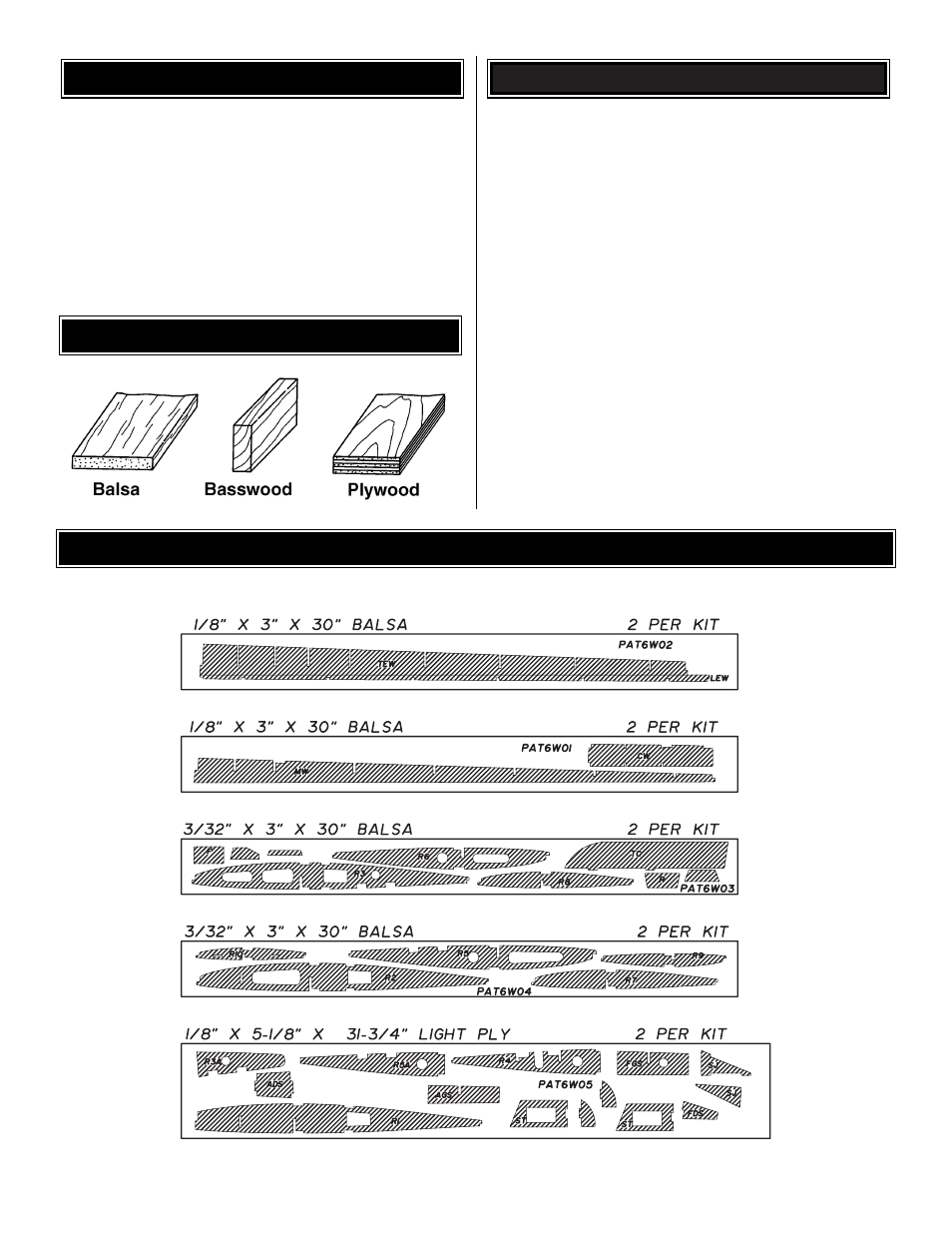
DIE-CUT DRAWINGS
- Avistar Elite .46 ARF - GPMA1005 (36 pages)
- Avistar Elite .46 RTF - GPMA1605 (20 pages)
- Big Stik 40 ARF MonoKote - GPMA1220 (24 pages)
- Cessna 182 Skylane 40 ARF - GPMA1228 (28 pages)
- Cherokee GP/EP ARF - GPMA1033 (28 pages)
- Christen Eagle 46 ARF - GPMA1431 (36 pages)
- Cirrus SR22 .46-55 ARF - GPMA1363 (32 pages)
- Citabria EP ARF - GPMA1127 (20 pages)
- Curtis P-6E Hawk EP Biplane ARF - GPMA1164 (24 pages)
- Dirty Birdy .60 ARF - GPMA1975 (44 pages)
- Easy Sport 40 ARF MonoKote - GPMA1036 (24 pages)
- Edge 540T EP ARF - GPMA1572 (24 pages)
- ElectroStik EP ARF - GPMA1574 (20 pages)
- ElectroStik EP RxR - GPMA7500 (16 pages)
- Escapade .61 GP/EP ARF - GPMA1201 (28 pages)
- Escapade EP/GP ARF - GPMA1200 (28 pages)
- Escapade MX 30cc ARF - GPMA1210 (32 pages)
- Escapade MX GP/EP ARF - GPMA1202 (24 pages)
- Evader EDF Sport Jet EP ARF - GPMA1800 (24 pages)
- Extra 300SP EP ARF - GPMA1188 (24 pages)
- Extra 300SP Performance Series ARF - GPMA1022 (28 pages)
- Extra 330SC EP ARF - GPMA1129 (20 pages)
- F1 Rocket Evo GP/EP ARF - GPMA1030 (28 pages)
- F-16 Falcon EDF ARF - GPMA1801 (24 pages)
- F-20 Tigershark Electric Ducted Fan ARF - GPMA1875 (16 pages)
- F-86 Sabre Micro EDF TxR - GPMA1771 (12 pages)
- Factor 3D ARF - GPMA1552 (20 pages)
- Fling ARF - GPMA1060 (16 pages)
- Fling DL ARF - GPMA1070 (16 pages)
- FlyLite EP Slow Flyer ARF - GPMA1107 (24 pages)
- Giant Big Stik ARF - GPMA1224 (32 pages)
- Giant Citabria 30cc/EP ARF - GPMA1435 (44 pages)
- Giant Revolver ARF - GPMA1425 (32 pages)
- Giant Super Sportster ARF - GPMA1044 (32 pages)
- Goldberg Super Chipmunk EP ARF - GPMA1928 (20 pages)
- Kunai 1.4M EP ARF - GPMA1815 (16 pages)
- Lanier RC Stinger II - GPMA1010 (24 pages)
- Matt Chapman Eagle 580 46/EP ARF - GPMA1281 (32 pages)
- Mister Mulligan EP ARF - GPMA1485 (32 pages)
- P-51 Mustang GP/EP ARF - GPMA1205 (24 pages)
- P-51 Mustang Sport Fighter .46 EP ARF - GPMA1208 (28 pages)
- PBY Catalina ARF - GPMA1154 (20 pages)
- Phazer EDF ARF - GPMA1802 (24 pages)
- Pluma 3D Bipe ARF ARF - GPMA1130 (24 pages)
- Proud Bird ARF - GPMA1260 (28 pages)