Great Planes Patriot XL Kit - GPMA0450 User Manual
Page 34
❏
8. Thread a nylon swivel clevis and retainer onto the 12"
[300mm] pushrod (threaded on one end). Connect the clevis
to the rudder torque rod and mark the point where the
pushrod crosses the rudder servo arm. Make a 90° bend at
that point in the pushrod. Insert the pushrod into the servo
arm. Snap in place using the nylon Faslink as shown. Trim
off all but about 1/16" [1.6mm] past the Faslink.
❏
9. Thread a nylon clevis and retainer onto the 12"
[300mm] pushrod (threaded on one end) for the elevator
pushrod. Slide the pushrod wires through the two elevator
pushrod guide tubes, which are on the left and right sides of
the fuselage. Remove the backing plate from a nylon
control horn and connect the horn to the clevis in the outer
hole. Fit the elevator to the stab, using the hinges to hold
them in place. DO NOT GLUE THE HINGES IN PLACE.
❏
10. Position the control horns on the elevators as shown in
the sketch and on the plan. Use a ballpoint pen to mark the
location of the control horn mounting holes and drill 3/32"
[2.4mm] holes at the marks. Temporarily mount the control
horn to the elevators with the backing plate and 2-56 x 5/8"
[16mm] screws.
❏
11. Attach the elevator pushrods to the servos with Faslinks
using the same procedure as you did with the rudder.
❏
12. Install the wing servos using the screws and hardware
provided by your manufacturer.
❏
13. Thread a nylon clevis and retainer onto each of the
four 6" [150mm] pushrods.
❏
14. Position the control horns on the ailerons and flaps as
shown on the plan. Use a ballpoint pen to mark the location of
the control horn mounting holes and drill 3/32" [2.4mm] holes
at the marks. Temporarily mount the control horn to the
ailerons with the backing plate and 2-56 x 5/8" [16mm] screws.
❏
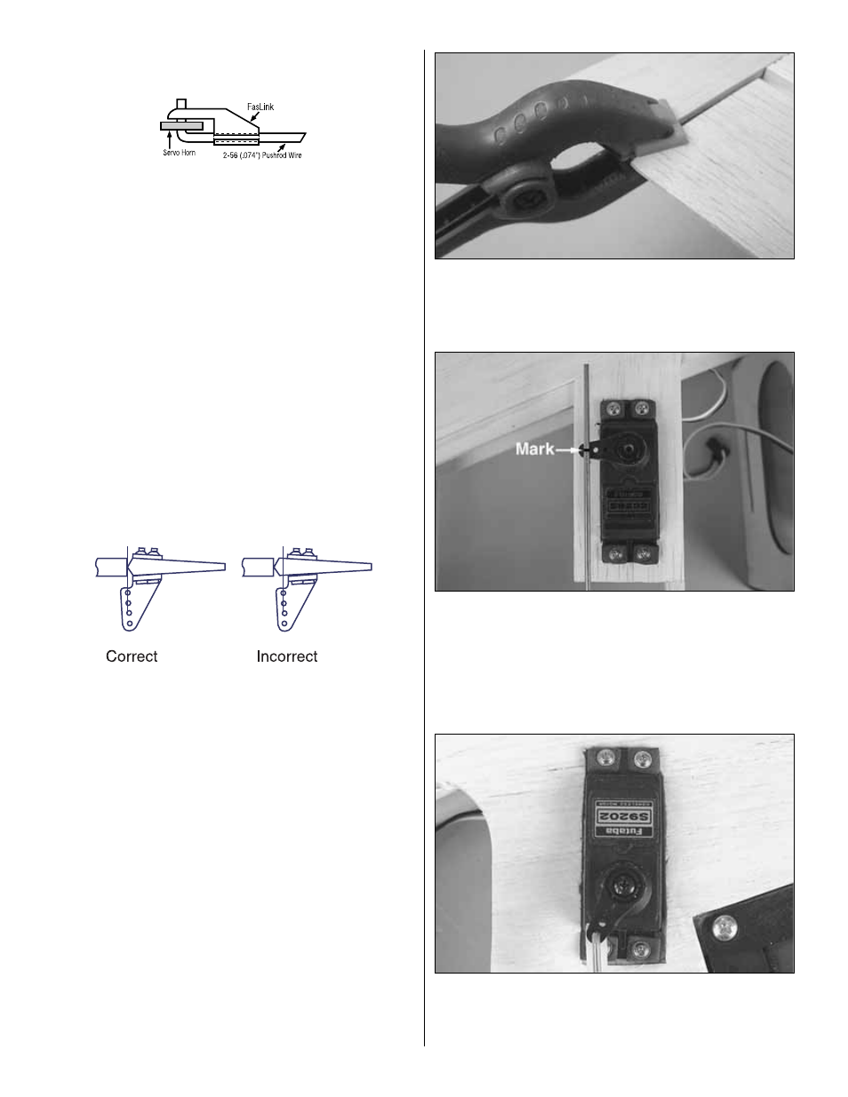
15. Connect the clevis to the control horn. Center the
ailerona and position the servo arms perpendicular to the
servo case. Hint: A small clamp can help hold the ailerons
even with the wing tip as shown.
❏
16. Align the pushrod with the outer hole on the aileron servo
arm. Mark the pushrod where it crosses the servo arm. Bend
the pushrod down 90° at the mark. Enlarge the hole in the servo
arm slightly with a 5/64" [2mm] drill bit and insert the pushrod.
❏
17. Install the Faslink first, then trim to 1/16" past the
bottom of the Faslink. Do this for both aileron servos.
❏
18. The flap linkages are done the same as the ailerons
with one difference. The servo arm on the flaps will be
angled toward the flap as shown. This will give you the angle
needed to deflect the flaps to their full extent.
34