Great Planes Patriot XL Kit - GPMA0450 User Manual
Page 37
❏
1. Reinstall the fuel tank, running the carb and vent lines out
of the holes in the firewall. Mark on the firewall with permanent
marker which line is vent and which line is carb (fuel).
❏
2. Connect the fuel lines to the carb and exhaust.
❏
3. Mount the landing gear to the fuselage.
❏
4. If you used pneumatic retracts, run all air tubing and
install the gear.
❏
5. Install the air cylinder for your retracts as shown using
the 1/8" [3mm] air tank holders. Push the ends of the air tank
holders in the slots and slide forward into place.
Do not confuse this procedure with “checking the C.G.”, which
will be discussed later in the manual. A model which is not
laterally balanced may exhibit a variety of unpleasant traits,
ranging from uncharacteristic tip stalls to problems with spin
entries. This aircraft, when balanced properly, exhibits none of
these tendencies. Be sure to check the lateral balance
carefully as described to help ensure that the model exhibits
the same exceptional handling qualities as our prototypes.
❏
1. With the wing level, have an assistant help you lift the
model by the engine propeller shaft and the bottom of the
fuse under the TE of the fin. Do this several times.
❏
2. If one wing always drops when you lift the model, it
means that side is heavy. Balance the airplane by adding
weight to the other wing tip. An airplane that has been laterally
balanced will track better in loops and other maneuvers.
❏
1. Remove all the pushrods and control horns from the
ailerons, elevators, and rudder. Remove the engine, engine
mount and any other hardware you may have installed
❏
2. Most of the model should be rough-sanded by now, with
all the tabs and rough edges sanded even. Fill all dents, seams,
low spots, and notches with HobbyLite
™
Balsa Colored Filler.
❏
3. After the filler has dried, use progressively finer grades
of sandpaper to even all the edges and seams and smooth
all surfaces. Remove all balsa dust from the model with
compressed air, a vacuum with a brush, or a tack cloth.
❏
4. If you used retracts, install the air hoses and mount the
air cylinder as shown.
❏
1. Install all servos using the hardware supplied by your
radio manufacturer.
❏
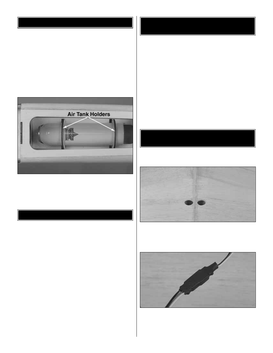
2. Cut two 3/4" [19mm] holes in the wing to route the
servo leads. If you look inside the wheel well, you can see
the hole in R5 that the servo leads will exit, make the holes
in the wing just above the exit in R5.
❏
3. You will need to attach a 6" [150mm] servo extension
to the aileron servos PRIOR to routing the servo lead. After
you have the 6" [150mm] extension attached, cover the
connection with heat shrink tubing (GPMM1070) and seal
together as shown.
FINAL SERVO AND
RECEIVER INSTALLATION
PREPARE THE MODEL
FOR COVERING
BALANCE THE MODEL LATERALLY
INSTALL THE HARDWARE
37