Great Planes F4 Phantom - GPMA0440 User Manual
Page 10
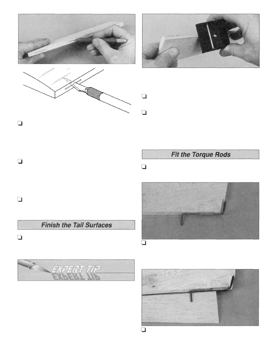
3. Cut the hinge slots in the elevator and stab using a
#11 blade. Begin by carefully cutting a very shallow slit at
the hinge location to accurately establish the hinge slot.
Make three or four more cuts, going a little deeper each
time. As you cut, slide the knife from side to side until the
slot has reached the proper depth and width for the hinge.
4. Cut the hinges for the elevators and rudder from the
supplied 2" x 9" hinge material. Use the hinge drawing
on the fuse plan as a guide. Trim off the corners and
temporarily join the elevators to the stabs with the hinges,
adjusting any hinge slots if necessary. Do not glue in the
hinges until you are instructed to do so.
5. Return to step 1 and use the same procedure to
hinge the rudder and fin.
of the elevators and rudder to a "V" shape as shown on
the plan.
CUT HINGE SLOT
WITH HOBBY KNIFE
AND #11 BLADE
1. Refer to the Expert Tip that follows and shape the LE
B. Using the bevel to lines and the centerline as a guide,
make the "V" on the leading edge of the elevators with a
razor plane or your bar sander.
2. Use the same procedure to bevel the leading edge of
the rudder.
3. Draw a centerline on the LE and tip of the stabs, and
on the fin's LE and tip. Sand a radius on the edges as shown
on the plan using the centerline as a guide to keep the radius
symmetrical. Do not round the TE of the stab or fin.
1. Position the stabs over the fuselage top view. Mark
the location of the torque rod bearings on the stabs.
2. Cut a slot in the TE of the stabs for the tab on the
torque rod bearings. Temporarily install the torque rods in
the stabs.
HOW TO BEVEL THE LEADING EDGE
A. Place the leading edge of one of the elevators on
your work surface and use your ballpoint pen to mark a
"bevel to" line on both sides about 1/8" high.
Note: You will probably have to adjust the height of the
elevator with card stock (as you did while marking the
centerline) so your "bevel to" line is not too high - making
too sharp of a "V."
3. With the stabs positioned on the plan, align the
elevators and mark the location of the torque rods.
10