Radio set-up, Final hookups and checks – Great Planes F-15 Eagle 40 Kit - GPMA0438 User Manual
Page 49
FINAL HOOKUPS AND CHECKS
(CG), and is centered where the main spar meets
rib #5 This is the balance point at which your
model should balance for your first flights. Later,
you may wish to experiment by shifting the balance
up to 1/2" forward or back to change the flying
characteristics Moving the balance forward may
improve the smoothness and arrow-like tracking,
but it may then require more speed for takeoff and
make it more difficult to slow down for landing
Moving the balance aft makes the model more
agile with a lighter and snappier "feel" If you move
the balance aft, the e l e v a t o r will have more
authority, possibly resulting in a plane that is too
maneuverable If this happens, you should reduce
the maximum elevator throw slightly In any case,
do not balance your model outside the
recommended range.
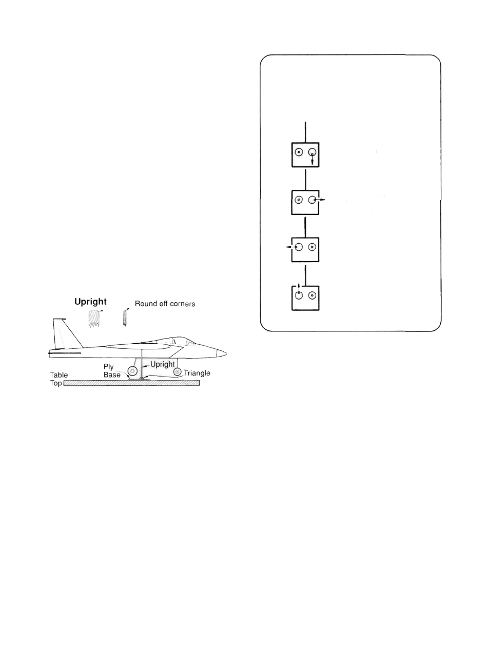
D 2. The best way to balance your F-15 is to
make a balancing stand from two squares of 1/4"
plywood and two 1/4" plywood uprights Mark the
fore and aft limits of the balance range on the
bottom of the wing (marking the limits on rib #6
will allow the balancing stand to rest against the
wing sheeting instead of open structure), and place
the airplane on the balancing stand with the fuel
tank empty Move the airplane forward or aft on
the stand until it balances with the stab level If it
balances outside the "balance range," you must
either shift the location of radio components (the
battery pack can be installed all the way up into the
compartment between F2 and F3 if needed) or add
weight to the nose or tail until it balances within the
range Tail weight may be added by using Great
Planes "stick-on" lead weights (GPMQ4485), and,
later, if the balance proves to be OK you can open
the fuse bottom and glue these in permanently
RADIO SET-UP
FOUR CHANNEL TRANSMITTER
Transmitter
Stick Movements
Control Surface
Movements
Elevator moves UP
Right aileron moves
UP and Left aileron
moves DOWN
Rudders move LEFT
Carburetor Wide Open
D 1 Make sure the control surfaces move in the
proper direction as illustrated in the sketch.
D 2. Check for wing twist as follows:
NOTE: Even if you have built your wing
on a perfectly flat surface and used
utmost care, it is possible that your
wing may have a twist due to uneven
shrinking of the covering material.
VERY IMPORTANT!: You must check
for this condition and correct it before
the first flight.
If you do not own a wing incidence meter, we
recommend that you purchase one from your local
hobby dealer or borrow one from another modeler
With the wing attached to the fuselage, block up
the fuselage until the stab is exactly level, then use
the incidence meter to check the angle of your
wing at the tips The meter should read minus
1-3/4° at the tips (this means that the trailing edge
is higher than the leading edge at both tips) If the
incidence meter reveals a deviation of more than
1/4 degree from the desired readings, you must
48