Great Planes F-15 Eagle 40 Kit - GPMA0438 User Manual
Page 20
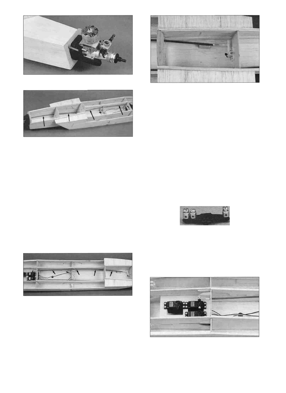
D 4. Determine where the throttle pushrod
should exit the firewall and drill a 3/16" hole there.
Route the throttle pushrod outer tube from the
firewall to former F5. We used a Great Planes
Semi-Flexible Pushrod (GPMQ3714). Cut the
outer tube to the correct length and remove it from
the plane. Scuff up the outside of the tube with
medium grit sandpaper, replace the tube and glue
it in place.
D 6. Assemble the nylon steering arm
(NYLON16) by inserting a 5/32" wheel collar
(WHCL005) inside the steering arm and securing it
with a 6-32 x 1/4" socket head cap screw
(SCRW007). Slide the 5/32" wire nose gear
(WBNT006) into the bearing, and through the
steering arm. Install a nylon clevis onto the plastic
inner pushrod using the 1" threaded rod that came
with the pushrod. Insert the inner pushrod into the
outer tube and snap the clevis onto the steering
arm. Slide the silicone retainer over the clevis.
Cut a scrap piece of balsa to support the end of
the steering outer tube and glue it in place on the
fuse bottom. Glue the steering outer tube to the
balsa piece but make sure the steering arm can
operate throughout its range without binding.
D 5. Install the nose gear steering pushrod
outer tube using the same technique outlined in
the last step. Notice that the outer tube extends to
within 1-7/8" of former F2. We used a Great
Planes Semi-Flexible Pushrod (GPMQ3714). If
you are using a different type of pushrod, just
adapt the instructions to fit your style of pushrod.
D 7. Install three Q u i c k - C o n n e c t o r s (Not
Included) on the rudder servo horn as shown in the
photo.
D 8. Install the horn on the rudder servo and
19