Fuselage assembly – Great Planes F-15 Eagle 40 Kit - GPMA0438 User Manual
Page 11
and 2" long, from the border of a die-cut 1/8" sheet.
Glue this piece to the inside of the stab tip. Sand it
to the contour of the stab as shown in the photo.
D 9. Trial fit all these parts together using the
torque rods and hinges. Check the operation of
the elevators, but do not glue anything yet.
sharpen the inside of one end of a 1/8" diameter
brass tube, and use it to cut this groove.
FUSELAGE
ASSEMBLY
PREPARE FUSE SIDES
D 6. Groove the stab TE to accept the torque
rod wire and nylon bearing tube. Ideally, the
torque rod should be centered on the elevator
hinge line. Use a sharpened 3/16" diameter brass
tube to cut the groove for the nylon bearing tube
and a 1/8" brass tube for the wire.
D 7. Using a sanding block and coarse (50 or
80-grit) sandpaper, sand both sides of each
elevator to a taper (see cross-section on plans).
The trailing edge should end up approximately
3/32" wide (Do not sand to a sharp edge). Leave
the ends square. Sand the leading edge of the
elevator to a "V-shape" as shown on the plan.
Sand the trailing edge of the stab tip to the same
taper as the elevator.
D D 1. Working over the fuselage side view
covered with waxed paper, trial fit a die-cut 1/8"
balsa forward fuse side (F154F02), forward
fuse side top (F154F03) and aft fuse side
(F154F01) together, sanding as necessary for a
good fit. Use a straight edge along the bottoms to
keep them aligned and glue them together.
NOTE: If this is your second time
through, remember to make a right and
a left side.
D D 8. Cut a piece of 1/8" balsa, 1/4" wide
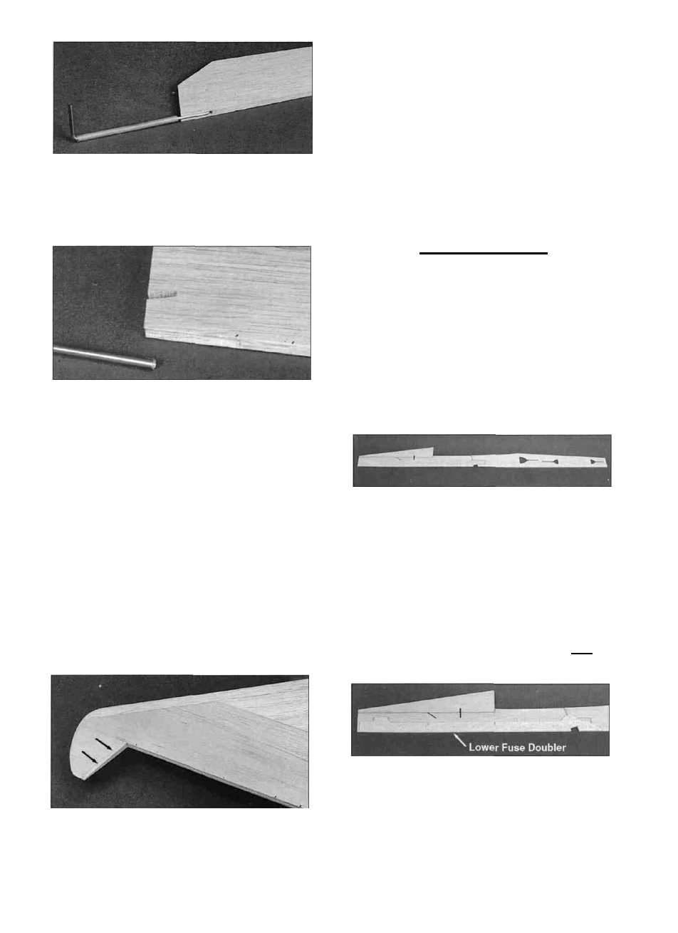
D D 2. Position a die-cut 3/32" balsa lower
fuse doubler (F154F11) by lining it up with the
landing gear block cut-out and the bottom of the
fuse side. Apply thin CA all around the doubler to
glue it in place.
10