Panel description, Front panel, Rear panel – Roland RSS-10 User Manual
Page 15: Front panel>
Attention! The text in this document has been recognized automatically. To view the original document, you can use the "Original mode".
PANEL DESCRIPTION
m^m
INPUT LEVEL Knobs A/B
INPUT LEVEL Indicators
OUTPUT LEVEL Indicators
Display Window
DEVICE ID Button
FUNCTION Button
OUTPUT Button
DEMO PROGRAM Button
POWER Switch
O
SOLND S^ACe P'
C
m
) =
POWER
□
O
O
FUNCTION Mode Indicators
OUTPUT Mode Indicators
DEMO Button
BYPASS Button
OPTION Button
LOCK Button
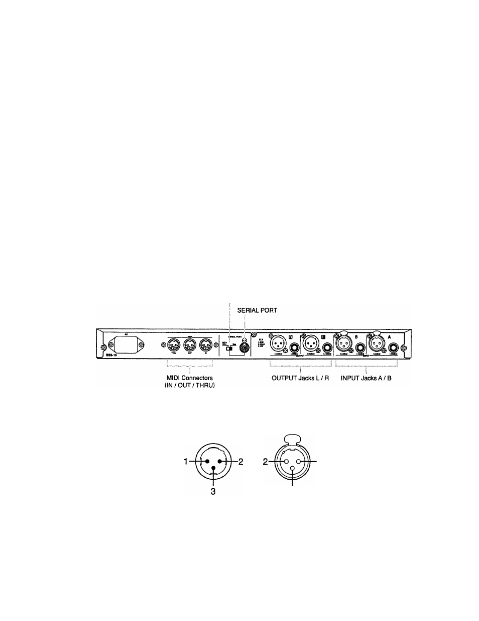
SERIAL PORT Switch
'
The following shows the pinout for the XLR Connectors. To set up an external unit with the RSS-
10, check the pin assignments for the unit.
1:GND
2:COLD
3:HOT
15