Electrical, Warning – FloAire STAGED ELECTRIC HEAT MODULE User Manual
Page 8
8
Copper Wire Ampacity
Wire Size AWG
Maximum Amps
14
15
12
20
10
30
8
50
6
65
4
85
3
100
2
115
1
130
1/0
150
2/0
175
3/0
200
4/0
230
250
255
300
285
350
310
400
335
500
380
600
420
Electrical
Before connecting power to the heater, read and understand
this entire section of this document. As-built wiring diagrams
are furnished with each fan by the factory, and are attached to
the door of the unit.
Electrical wiring and connections should be done in accordance
with local ordnances and the National Electric Code,
ANSI/NFPA70. Be sure the voltage and phase of the power
supply and the wire amperage capacity is in accordance with
the motor nameplate. For additional safety information refer to AMCA publication 410-96, Recommended
Safety Practices for Users and Installers of Industrial and Commercial Fans.
WARNING: ELECTRIC HEATERS HAVE TWO POWER INPUTS. THE EXTERNAL
DISCONNECT INTERRUPTS POWER TO THE MOTOR AND CONTROLS ONLY.
THE ELECTRIC COIL POWER IS INTERRUPTED BY THE DISCONNECT SWITCH
ON THE ELECTRIC COIL DOOR.
1. Always disconnect power before working on or near a
heater. Lock and tag the disconnect switch or breaker to
prevent accidental power up.
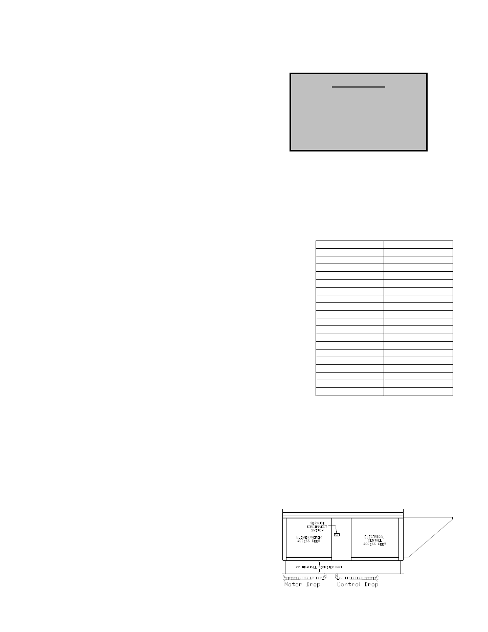
2. An electrical drop containing the motor power wiring is
shipped with every fan. The electrical drop should be brought
through one of the conduit openings located in the base of the
unit, run through the curb, and connected to a junction box
inside the building.
3. A dedicated branch circuit should supply the motor circuit with
short circuit protection according to the National Electric Code.
This dedicated branch should be run to the junction box
mentioned above and connected as shown in a following
illustration labeled “Fan to Building Wiring Connection”.
4. A separate power source should supply the electric coil
power. Power from the building breaker should be wired
directly to the coil disconnect. This should be done using wire
of the proper gauge as indicated on the wire ampacity chart to
the right. A hole must be drilled in the fan enclosure to
properly run the electric coil power.
5. Make certain that the power source is compatible with the requirements of your equipment. The
heater nameplate identifies the proper phase and voltage of the motor and coil.
6. Units shipped with an optional remote panel have two electrical circuit drops. It is important to
run the motor wires in a separate conduit from the remote control wiring. The DC wires from the
unit temperature controller, located in the control drop, should be shielded cable or run in a
separate conduit.
7. Before connecting heater to the building power source, verify power line wiring is de-energized.
8. Secure the power cables to prevent contact with sharp objects.
9. Do not kink power cable and never allow the cable to come in contact with oil, grease, hot
surfaces or chemicals.
10. Before powering up the heater, check fan wheel for
free rotation and make sure that the interior of the
heater is free of loose debris or shipping materials.
11. If any of the original wire supplied with the heater
must be replaced, it must be replaced with type
THHN wire or equivalent.
WARNING!!
Disconnect
power
before
installing or servicing fan. High
voltage
electrical
input
is
needed for this equipment. This
work should be performed by a
qualified electrician.