Sequence of operation, Main circuit – FloAire STAGED ELECTRIC HEAT MODULE User Manual
Page 14
14
Main Power
Supply
External
Disconnect
Switch
On
Off
Nothing
Happens
Freeze-Stat
Powered
Discharge
Temperature
Blower Shuts Down
After Time Setting
on Freeze-Stat
Passes
Motorized
Damper Actuator
Energized
Colder Then
Freeze-Stat
Set-Point
Warmer Then
Freeze-Stat Set-Point
No Freeze-
Stat
Provided
Damper End
Switch
Damper Opens,
Nothing Else
Happens
Supply Motor
Contactor is
Energized, Motor
Starts
End Switch
Makes
End Switch
Does Not
Make
No Damper
Provided
No Freeze-Stat
or
Damper Provided
Coil Blower
Interlock Relay is
Energized
Coil
Disconnect
Switch
On
Off
No Heat
Air flow Switch
Energized
No Heat - Not
Enough Airflow
No
Yes
Yes
Outside Air
Temperature
No
No Heat
Requirement
Coil Step Controller
is Energized -
Heating Begins
Normal Operation
Cooler Then Thermostat
Set-Point
Warmer Then
Thermostat
Set-Point
Blower Interlock
Energized
No
No Heat - No Power to
Blower Interlock Relay -
Follow Flow Chart to Left
Thermal Limit
Tripped
Overheat Situation -
Not Enough Airflow
Yes
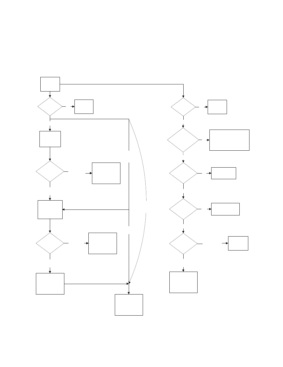
Sequence of Operation
The main power supply provides power to both the motor controls and the coil. The blower interlock relay
is the common link between the two circuits, as shown below. Once in normal operation, the coil
modulating stage will energize first and then subsequent power stages as required.
Main Circuit