Components – FloAire STAGED ELECTRIC HEAT MODULE User Manual
Page 16
16
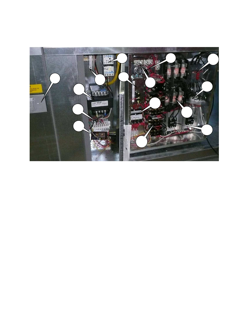
Components
The following image and list outlines the common electric heater components and their functions.
1. Motor Disconnect Switch – Interrupts power to blower motor and controls.
2. Motor Starter – Contactor with overload protection to start and protect motor.
3. Power Transformer – Installed when motor voltage > 120V. Used to provide 120V service to
controls.
4. Freeze-Stat Thermostat (Optional) – De-energizes blower motor if the discharge air
temperature falls below the set point.
5. Terminal Strip – Central location to terminate control wiring. Should be used for troubleshooting.
6. Airflow Switch – A safety device insuring proper air flow during coil operation.
7. Circuit Breaker – Protects electrical components from high current spikes.
8. Automatic Reset Thermal Limit – Safety device that prevents the coil from overheating.
9. Coil Termination – Wire connection to coil element.
10. Coil Contactor – Energizes coil when there is a signal from step controller.
11. Line Fuse – Fuse protecting coil from over amperage.
12. Control Transformer – 120V primary; 24V secondary control transformer.
13. Coil Disconnect Switch – Interrupts power to electric coil.
14. Stage Controller – Controls multiple heating stages in a pre-determined sequence. Works in
conjunction with a proportional thermostat (not shown). A sensor is mounted in blower for
discharge control. The set-point is mounted remotely for either space control or discharge
control.
15. SCR – Modulates power to the electric coil.
1
2
3
5
15
14
13
6
12
11
9
8
4
7
10