EVCO EC6295S001 User Manual
Page 4
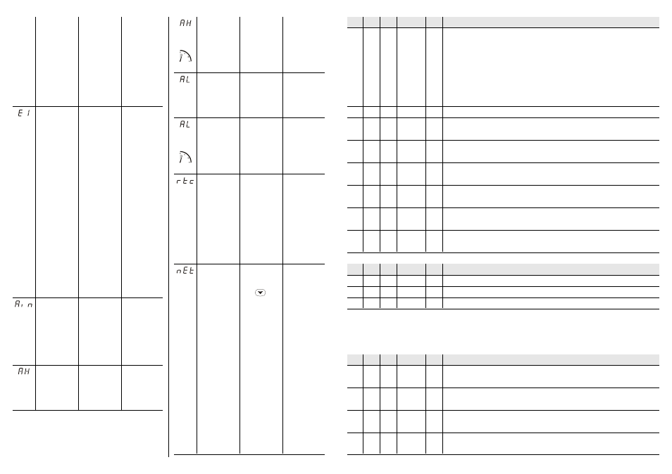
evapora-
tor probe
alarm
multi-
function
input
alarm
upper
tempera-
ture alarm
• the connection in-
strument-cabinet
probe is wrong
• the cabinet tempera-
ture is outside the
limits allowed by the
working range of
the instrument
• the kind of evapora-
tor probe you have
connected is not
right
• the evaporator
probe plays up
• the connection in-
strument-evaporator
probe is wrong
• the evaporator tem-
perature is outside
the limits allowed by
the working range
of the instrument
the multifunction input
is active.
Unless the parameter
i6 has value 1, the in-
strument will not show
any indication
the cabinet tempera-
ture is outside the limit
you have set with the
parameter A1b
• test the temperature
close to the probe (it
has to be between
the limits allowed by
the working range)
• look at the param-
eter /0
• test the integrity of
the probe
• test the instrument-
probe connection
• test the temperature
close to the probe (it
has to be between
the limits allowed by
the working range)
deactivate the input
(look at the parameters
i0, i1 and i6)
test the temperature
close to the probe
(look at the parameters
A0, A1b and A2b)
• if the defrost is run-
ning, it will immedi-
ately end
• the defrost will
never be activated
• if the parameter dE
has value 2, the in-
strument will work
as if the parameter
had value 0
• if the parameter F7
has value 3 or 4, the
evaporator fan will
work in accordance
with the compres-
sor, except what
you have set with
the parameters F4
and F5
• the defrost will end
by time (parameter
d3)
you will get the action
you have chosen with
the parameter i0
no effects
for 3 s
every 4
lower
tempera-
ture alarm
for 3 s
every 4
real time
clock
alarm
slave
alarm
there has been an up-
per temperature alarm
the cabinet tempera-
ture is outside the limit
you have set with the
parameter A1A
there has been a lower
temperature alarm
there is the corruption
of the data of the clock
of the instrument
the instrument will be
set as slave, among
the remote controls,
coming from the mas-
ter, the slave has to
implement there will
be the comp. status
and there will be one
of the alarms you saw
in the previous cases.
If the master is in the
STAND-BY mode and
the slave is ON, the in-
dication will be
showed every 2 s alter-
nated with the alarm
code
look at the parameters
A0, A1b, A2b, A8 and
A9
test the temperature
close to the probe
(look at the parameters
A0, A1A and A2A)
look at the parameters
A0, A1A, A2A, A8 and
A9
set the clock again
• if you have to show
the alarm code,
press
• look at the remedies
of that case
no effects
no effects
no effects
• if the parameter dE
has value 3, the in-
strument will work
as if the parameter
had value 0
• the Energy Saving
cycle will never be
activated
look at the effects of
that case
LABEL MIN. MAX. U.M.
DEF. DIGITAL INPUTS
i0
0
7
---
4
action given by the multifunction input activation (0 = inactive, 1 = once d5 has passed, the
defrost will be activated
(7)
, 2 = the cabinet light will be turned ON, 3 = the compressor will be
forced ON for A5 and the cabinet light will be turned ON, 4 = the compressor and the
evaporator fan will be forced OFF for A5 and the cabinet light will be turned ON,
5 = the evaporator fan will be forced OFF for A5 and the cabinet light will be turned ON,
6 = the working setpoint becomes r8, 7 = the working setpoint becomes r8 and the cabinet
light will be turned OFF); look at i7 as well
i1
0
1
---
0
kind of contact of the multifunction input (it is important if i0 ≠ 0; 0 = NO, 1 = NC)
i2
1
2
---
1
action given by the lock input/thermal protection activation (1 = the compressor will be forced
OFF, 2 = in accordance with i3, i4 and i5)
i3
0
15
---
0
lock input/thermal protection alarms number such as to give the lock of the instrument (it is
important if i2 = 2; 0 = the lock of the instrument will never take place)
i4
i5
240
min
0
time without lock input/thermal protection alarms able to clear the lock input/thermal pro-
tection alarms counter (it is important if i2 = 2)
i5
0
15
(14)
min
0
minimum delay between the lock input/thermal protection deactivation and the following
compressor activation (it is important if i2 = 2)
i6
0
1
---
1
indication “Ain” flashing on the display during the multifunction input activation (it is impor-
tant if i0 ≠ 0)
i7
0
240
min
0
delay between the multifunction input deactivation and the cabinet light gets OFF (it is
important if i0 = 2, 3, 4 or 5)
(15)
LABEL MIN. MAX. U.M.
DEF. SERIAL NETWORK (EVCOBUS)
L1
1
15
---
1
instrument address
L2
0
7
---
0
instrument group
L4
0
3
---
1
baud rate (0 = 1,200 baud, 1 = 2,400 baud, 2 = 4,800 baud, 3 = 9,600 baud)
LABEL MIN. MAX. U.M.
DEF. SERIAL NETWORK (EVCONET)
n0
0
2
---
0
operation of the instrument in the network (0 = instrument not enabled to work in the
network, 1 = master, 2 = slave)
(16)
n1
0
8
---
0
address of the instrument in the network (it is important if n0 ≠ 0; 0 = master address,
1 ... 8 = first ... eighth slave address)
n3
0
1
---
0
authorization to implement the remote controls coming from the master (it is important if
n0 = 2 and n1 ≠ 0; 1 = YES)
n4
0
240
s
0
time between the master implements a control and the slave implements the same control (it
is important if n0 = 2 and n1 ≠ 0); look at nA as well
(17)
(18)